Wednesday, April 17, 2013

Datsun F10, 200SX & B210 1976-77 Brake Repair Manual

DESCRIPTION
Brake system is hydraulically operated, utilizing a tandem master cylinder and a Master-Vac power brake unit. Front disc brakes consist of rotors attached to wheel hubs, and single cylinder, dual-piston, floating-calipers attached to steering knuckles. Rear brakes are leading-trailing shoe/drum type, using a single piston sliding wheel cylinder. Parking brake is cable actuated; operating wheel cylinders of rear brake assemblies.

ADJUSTMENT
PEDAL HEIGHT & FREE PLAY
F10 - Adjust pedal height to 6.8-7.0" (172-178 mm) by turning nut on master cylinder push rod. Adjust stop light switch so pedal just touches end of stop light switch; tighten lock nut. NOTE - Brake pedal should be checked for travel and smooth operation. Travel should be 5-5.25" (127-133 mm).
200SX - Adjust pedal height to about 6.9" (175.5 mm) using stop light switch. Lock switch in place with retaining nut. After pedal height is adjusted, loosen push rod lock nut and adjust pedal free play to .039-.118" (1-3 mm).
B210 - Adjust pedal height to specifications by moving stop lamp switch. Pedal height should be 6.14" (156 mm) on vehicles equipped with manual transmission and 6.22" (158 mm) on vehicles with automatic transmission. After pedal height is adjusted, loosen push rod lock nut and adjust pedal free play to .039-.197" (1-5 mm).
FRONT DISC BRAKE PADS
Front disc brakes are self-adjusting, therefore, no adjustment in service is required.
REAR BRAKE SHOES
F10 - Raise and support vehicle. Pump brake pedal several times to center brake shoes. Using a screwdriver, turn adjuster star until considerable drag is evident. Back off adjuster five or six notches and make sure drum rotates freely.
200SX - No adjustment required.
B210 - Raise and support vehicle. Using a suitable brake adjusting tool, tighten adjuster eccentric clockwise until brake shoe contacts drum. Return adjuster eccentric until shoe is slightly separated from drum. Check operation by turning drum and applying brakes; if shoe interferes with drum rotation, readjust.
PARKING BRAKE
With rear brakes properly adjusted, adjust parking brake cable turnbuckle until rear brakes are locked when parking brake lever is pulled to sixth or seventh ratchet stop. Release parking brake lever and ensure rear wheels turn freely and that all parts are returned to their original position.
COMBINATION VALVE
Function Test, All Models - Accelerate engine to 30 mph and rapidly apply brakes. If rear wheels lock before front wheels, malfunction of combination valve assembly (200SX & B210), or of separate proportioning valve (F10) is indicated.
Warning Light Operation & Reset, Except 200SX - 1) Instrument panel light will come on when a pressure difference of between 71-224 psi is evident between front and rear hydraulic systems. Combination valve  shuffle moves to side of low pressure and grounds electrical circuit, causing warning light to come on.
2) When hydraulic problem has been corrected and brakes have been bled, system should have 427 psi. Shuttle will then return to position and light will go out.
HYDRAULIC SYSTEM BLEEDING
Attach a bleed tube to bleeder screw and immerse opposite end of tube in a container partially filled with brake fluid. Pump brake pedal two or three times, keep pedal fully depressed, open bleeder screw and exhaust air, close bleeder screw, and return brake pedal. Repeat operation until air bubbles are no longer seen in discharged fluid. Repeat procedure on remaining brake lines. Bleed rear wheels first, then front wheels.

REMOVAL & INSTALLATION
FRONT DISC BRAKE PADS
Removal - Raise front of vehicle and support in place, then remove front wheels. Remove clips from retaining pins and pull out pins, coil springs and pad springs. Remove  pads from caliper assembly using a suitable pair of pliers.
Inspection - With friction pads removed, measure their thickness. Replace any pad that is worn to less than .063" (1.6 mm) in thickness (not including metal backing plate). It is recommended that friction pads be replaced as a set to prevent any possibility of uneven braking
NOTE - Replace all pads at same time.
Installation - Clean and apply P.B.C. grease (or equivalent) on yoke groove of cylinder body, sliding contact portions of yoke and end surface of piston. Loosen bleeder screw and push outer piston in cylinder until end surface of piston coincides with end surface of retaining ring on boot. Install inner brake pad. Push inner piston in cylinder by pulling on yoke, then install outer brake pad. After installing pads, depress brake pedal several times to seat pads.
FRONT DISC BRAKE CALIPER
Removal - Raise vehicle and suitable support on safety stands; remove tire and wheel. Remove brake friction pads as previously described. Disconnect brake line from wheel cylinder. To ease removal of caliper, remove strut assembly and knuckle arm mounting bolt. Withdraw caliper mounting bolt and separate it from strut assembly.
Installation - To install brake caliper assembly, reverse removal procedures, noting the following: Bleed hydraulic system.
FRONT DISC BRAKE ROTOR
Fig. 1 Exploded View of Datsun 200SX Rear
Brake Assembly
Removal - With caliper removed, remove hub dust cap, cotter pin and nut. Remove hub and rotor assembly with wheel bearing and washer in place. Remove bolts attaching rotor to wheel hub, and separate rotor from hub.
Installation - Reverse removal procedure, tighten rotor-to-hub bolts securely, and adjust wheel bearings. Use a dial indicator to measure rotor runout. Resurface rotor if runout exceeds .0047" (.12 mm) for 200SX & B210 or .006" (.15 mm) for F10.
REAR BRAKE ASSEMBLY
Removal (Rear) - Raise vehicle and suitable support on safety stands; remove tire and wheel. Loosen parking brake linkage at clevis pin and place out of way. Remove brake drum. Remove shoe retainer and return spring, then lift off shoe assembly. Disconnect brake line from wheel cylinder. If necessary, wheel cylinder can now be removed by taking out mounting bolt.
Inspecting - Inspect all brake components for damage or excessive wear and replace those found defective. Replace brake lining if it is oil soaked or lining is less than .059" (1.5 mm) thick.
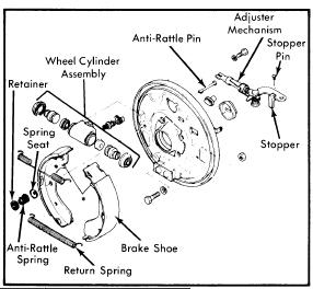
Fig. 2 Exploded View of F10 and B210  Rear
Brake Assembly - 200SX Similar
Installation - To install rear brake lining, reverse removal procedures, noting the following:  Readjust shoe-to-drum clearance and, if necessary, bleed hydraulic system.
MASTER CYLINDER
Removal - Disconnect any electrical leads attached to cylinder reservoir. Disconnect front and rear brake lines from master cylinder outlet ports. On models equipped without power brakes, separate master cylinder push rod from pedal. Remove cylinder mounting nuts and slide unit off stud. Make sure brake fluid does not drop on point
NOTE - On F10 models, fluid reservoir can be removed attached to cylinder.
Installation - To install master cylinder, reverse removal procedures, noting the following: Bleed hydraulic system and check pedal height.
POWER BRAKE UNIT
Removal - Disconnect power unit push rod from brake pedal by removing clevis pin. Disconnect hydraulic lines from master cylinder and vacuum line from power unit, remove master cylinder attaching nuts, and remove master cylinder. Remove nuts attaching power unit to firewall, and remove power unit from engine compartment.
Installation - Reverse removal procedure, adjust brake pedal height, and bleed hydraulic system.
Check Valve Removal - Check valve is located in vacuum line between intake manifold and power unit on firewall. To remove, disconnect retaining clip from firewall, remove hose clamps, separate hoses from valve, and remove check valve. To install, reverse removal procedure.

OVERHAUL
Fig. 3 Exploded View of Front Disc Brake Caliper

FRONT DISC BRAKE CALIPER
Disassembly - With caliper removed, drain brake fluid and remove bleeder screw. Push both pistons into cylinder bore, then place yoke in a vise and tap the top of yoke lightly with a hammer to separate cylinder from yoke. Remove bias ring from outer piston, then remove retaining rings and boots. Push both pistons out in one direction. Remove piston seals from cylinder and yoke spring from yoke.
Inspecting - Thoroughly clean all internal parts and check each component fro excessive wear or damage. If caliper bore is damaged or excessively rusted, it must be replaced. If however, slight imperfections are evident, honing will eliminate them. It is recommended to replace all seals when overhauling.
Reassembly - Before assembling components, lightly coat with suitable brake grease. Insert bias ring into piston so round portion of ring fits to bottom of piston. Insert piston into cylinder. Do not fully seat piston. Install dust boot and retaining ring. Install yoke bias ring so it coincides with yoke groove of cylinder. Fit bias spring to yoke so bias spring faces bleeder side of cylinder. With yoke spring inserted in cylinder groove, properly align position of bias spring so groove of spring aligns with yoke. Assemble body-to-yoke, tapping lightly if necessary.
Fig. 4 Exploded View of Datsun Wheel Cylinder
Used on F10, 200SX and B210 Models
MASTER CYLINDER
NOTE - On F10 models, separate reservoir tank assembly.
Disassembly - Remove master cylinder reservoir caps and filters and drain brake fluid. Using a screwdriver, pry off stopper ring. Remove stopper screw and pull out primary piston assembly, spring and secondary piston assembly. Remove plugs and pull out front and rear check valves.
NOTE - On all except F10 models, do not remove reservoir tanks. If tanks are removed for any reason, discard and install new ones.
Inspecting - Thoroughly clean all components in approved grade brake fluid. Inspect all components for excessive wear or damage and replace parts as necessary.
Reassembly - Reverse disassembly procedure and note the following: Coat all parts with brake fluid (rubber parts with brake grease) when assembling.
Fig. 5 Exploded View of Datsun 200SX and B210
Master Cylinder - F10 Models Have Different
Reservoir Arrangement
POWER BRAKE UNIT
Disassembly - 1) Place power unit in a soft jaw vise with operating rod pointing up. Scribe an alignment mark on front and rear shell to assure reassembly in original position, then remove lock nut, clevis and dust boot from rear shell.
2) Place suitable wrench (ST08080000) over rear shell mounting studs. Press down on wrench while
rotating counterclockwise and remove rear shell, then lift out diaphragm plate assembly, diaphragm spring and push rod assembly. Pry off retainer and remove bearing and valve body seal assembly.
3) Remove diaphragm from diaphragm plate assembly, then pry off air silencer retainer and remove silencer and filter. Rotate diaphragm plate assembly until valve plunger key slot is down, then press in on plunger and shake out stop key. Remove reaction disc from plate assembly. Detach flange from front shell and remove front seal assembly.
Cleaning & Inspection - Clean all parts in denatured alcohol and blow dry with compressed air. Inspect front and rear shells for wear or damage. If slight rust is found on inside surface of shells, polish clean with fine emery cloth. Inspect all parts for cracks, nicks, distortion or other damage and replace as necessary.
Reassembly - Reverse disassembly procedure and note the following: Apply a thin coat of silicone grease to parts before installation. When assembling front shell to rear shell, ensure marks made during disassembly are aligned. After reassembly, measure distance from master cylinder mounting surface of power unit to end of power unit push rod; distance should be .38-.39" (9.8-10.0 mm). If distance is not to specifications, correct by adjusting end of push rod.


Fig. 6 Sectional View of Datsun Master Vac


Tuesday, April 16, 2013

Datsun 710 & 810 1976-77 Brake Repair Manual

DESCRIPTION
Brake system is hydraulically operated, using a tandem master cylinder and a Master-Vac power brake unit. Front brake are single cylinder, dual piston type. Rear brakes are leading-trailing drum type. A combination valve is used in brake system to prevent premature locking of rear brakes. Parking brake is cable operated by an actuating lever. Parking brake works on wheels only.

ADJUSTMENT
BRAKE PEDAL HEIGHT & FREE PLAY ADJUSTMENT
Adjust brake light switch bolt until end face is flush with front force of bracket, then tighten lock nut. Adjust pedal stopper until pedal height, measured from pedal pad to floor, is 7.28" (185 mm) for 710 models or 7.09" (180 mm) for 810 models. Adjust master cylinder push rod length until free play, measured at pedal, is .039 - .197" (1-5 mm).
FRONT DISC BRAKE PADS
Front disc brakes are self-adjusting; therefore, no adjustment in service is required.
REAR BRAKE SHOES
710 - With parking brake fully released, depress brake pedal several times so that shoes are settled to normal positions. Turn adjusting cam on backing plate until shoes lock against drum. Loosen adjusting cam until drum is just free to rotate.
810 - No adjustment is required. Brakes are adjusted when parking brake is applied.
PARKING BRAKE
Station Wagon - Make sure rear brakes are correctly adjusted. Adjust front cable adjusting nut so that
Fig. 1 Adjusting Center Lever (Sedan Models)
when parking brake lever is pulled with specified force (see specifications); the lever stroke or the number of notches is specified (see specifications). With parking brake off, make sure cables are slack and the rear levers are in their original positions.
Sedan - Make sure rear brake are correctly adjusted. Adjust front cable adjusting nut so that when parking brake is off, dimension "A" (see Fig.1) is 28 (7 mm). Now adjust rear cable adjuster so that when parking brake lever is pulled with specified force (see specifications) the lever stroke or the number of notches is as specified (see specifications). With parking brake off, make sure cables are slack and the rear levers are in their original positions.
                               Parking Brake Adjustment Specifications
Adjustment                            Station Wagon                     Sedan
Pulling Force ..........................  53 lbs (24 kg)...................  44 lbs (20 kg)
Lever Stroke...........................   4.49"................................ 4.02-4.49"
                                               (114 mm).......................... (102-114 mm)
No. of Notches..........................  6  .................................    5-6
"Pulling Force" - Measured 1.97" (50 mm) from the end of the parking brake lever (less release button)

BRAKE WARNING LIGHT
Brake Warning Light - Light indicates, parking brake is engaged. To adjust warning light, bend switch plate down until light operates when ratchet handle is pulled up one notch and so light goes out when handle is returned to normal position.
COMBINATION VALVE
Function Test - Accelerate to about 30 mph on a dry concrete surface and harshly apply brakes. If rear wheels lock at same time as fronts do, or if front wheels lock before rears, combination valve is malfunctioning; replace valve.
Warning light Operation & Reset - Instrument panel light will come on when a pressure difference of between 71-224 psi is evident between front and rear hydraulic systems. Combination valve shuttle moves to side of low pressure and grounds electrical circuit causing warning light to come on. When hydraulic problem has been corrected and brakes have been bled, system should have 427 psi. Shuttle will then return to centered position and light will go out.
HYDRAULIC SYSTEM BLEEDING
Attach a bleed tube to bleeder screw and immerse opposite end of tube in container partially filled with brake fluid. Depress pedal, open bleeder allowing air to escape, close bleeder screw, and allow pedal to return slowly. Continue operation until air bubbles are no longer seen in discharged fluid. Repeat procedure on remaining brake lines until all air is bled from system. Bleeding sequence is: Master cylinder first, rear brakes, and front brakes.

REMOVAL & INSTALLATION
FRONT DISC BRAKE PADS
Removal - Raise and support front of vehicle. Remove retaining spring clip. Remove disc pad pins retaining anti squeal springs. Pull pads from caliper cavity. If pad thickness is less than .079" (2 mm), replace pads.
NOTE - Pads must always be replaced in sets.
Installation - Clean cavity and area surrounding caliper. Loosen bleeder screw and seat outer piston  in cylinder until dust seal groove of piston aligns with end surface of retaining ring on dust seal. NOTE - Make sure piston groove does not go inside piston seal. Tighten bleeder screw and fit new inner pad. Force inner piston into cylinder and install new outer pad. Install anti-squeal spring and insert pad pins, then put spring clip into position.
FRONT DISC BRAKE CALIPER
Removal - Raise and support vehicle and remove tire and wheel assembly. Disconnect hydraulic line from caliper and plug openings. Remove bolts securing caliper to steering knuckle and remove caliper.
Installation - Reverse removal procedure, tighten mounting bolts securely, and bleed hydraulic system.
FRONT DISC BRAKE ROTOR
Removal - With caliper assembly removed, remove hub dust cap, adjusting cap, adjustment nut and washer. Slide hub and rotor assembly from spindle taking care not to lose outer wheel bearing. Remove bolts attaching rotor to hub, then separate.
Installation - Reverse removal procedure, tighten rotor mounting bolts securely, and adjust wheel bearings. Using a dial indicator, measure rotor runout. If runout exceeds .005" (.12 mm), resurface or replace rotor.
REAR BRAKE SHOES

Removal 710 - Raise and support vehicle, remove tire and wheel. Remove brake drum. Disconnect See Fig. 2
Fig. 2 Rear Brake Assembly for Datsun 710
Also Note Detail of Sliding Wheel Cylinder
for Disassembly Purposes
anti-rattle springs and shoe return springs. Take shoes off backing plate. If necessary, remove bolts, securing adjuster to backing plate and remove adjuster mechanism.
Installation - Reverse removal procedure and note the following: Apply grease to sliding areas of backing plate and adjuster, taking care not to contaminate linings. When installed, adjust brake shoes, parking brake, and bleed hydraulic system.
Removal 810 Sedan - 1) Raise rear of vehicle, remove tire and brake drum. Apply parking brake. Lightly tap stopper head. Remove stopper and fastener as an assembly. Release parking brake.
2) If necessary, remove rear axle to gain access to rear brake components. Remove anti-rattle spring and pin. Remove return springs and brake shoes. Remove parking brake cable from lever. Pry off snap ring and remove lever from brake shoe.
Installation - To install, reverse removal procedure. Apply grease to adjuster nut and threads on rod. Also, apply grease to mating surfaces between adjuster and back plate.
Fig. 3 Exploded View of Rear Brake Assembly
for Datsun 810 Sedan Models. 810 Station Wagon
Models Are Similar But Have Different Brake
Adjuster Mechanism Configuration
Removal, 810 Station Wagon - 1) Raise rear of vehicle, remove tire and brake drum. Apply parking brake. Pull out pin and remove stopper from toggle lever. Release parking brake.
2) If necessary, remove rear axle shaft to gain access to brake components. Remove anti-rattle spring and pin. Remove return springs and brake shoes. Remove parking brake return spring, then remove cross-end cotter pin. Remove dust cover and toggle lever with adjuster assembly.
Installation - To install, reverse removal procedure. Apply grease to adjuster nut and rod threads. Also apply grease to mating surface between adjuster and toggle lever.
Removal, 710 - With rear drum and brake shoes removed, disconnect and plug hydraulic line at wheel cylinder. Pull out clevis pin and separate rod from cylinder operating lever. Remove dust cover, adjusting shims and lock plated, then remove wheel cylinder.
Installation - Reverse removal procedure and note the following: After wheel cylinder is installed, measure wheel cylinder sliding resistance using a spring pull gauge; resistance should be 4.4-15.4 lbs. (2.0-7.0 kg.). Install brake shoe assemblies and bleed hydraulic system.
Removal, 810 - With brake drum and shoes removed, disconnect hydraulic line at rear of wheel cylinder. Remove bolt securing wheel cylinder to backing plate and remove cylinder.
Installation - To install, reverse removal procedure. Bleed hydraulic system after installation.
MASTER CYLINDER
Removal - Disconnect and plug front and rear hydraulic lines from master cylinder and drain brake fluid from cylinder. Remove master cylinder attaching nuts and lift off master cylinder.
Installation - Reverse removal procedure and bleed hydraulic system.
POWER BRAKE UNIT
Removal - With master cylinder removed, disconnect vacuum line from power unit. From inside vehicle, disconnect pedal return spring, push rod from brake pedal, and power unit mounting nuts. Remove power unit from engine compartment.
Installation - Reverse removal procedure, adjust pedal height and free play, and bleed hydraulic system.
Check Valve Replacement - Check valve is located near identification plate on firewall. To remove, disconnect clip, remove hose clamps, separate hoses from valve, and remove valve. To install, reverse removal procedure.

OVERHAUL
FRONT DISC BRAKE CALIPER
Fig. 4 Exploded View of Front Disc Brake
Caliper. 710 Caliper is Shown. - 810 Models
Have Slightly Different Holder Pins and
Anti-Rattle Springs
Disassembly - Drain any remaining fluid from cylinder. Remove holding mounting nut. See Fig. 4. Separate yoke and cylinder body. Remove yoke holder from piston. Take off retaining ring and dust seals from both inner and outer pistons. Force pistons from cylinder using compressed air. Carefully pry out piston seals.
Inspection - Clean all components in brake fluid. Inspect rust, score marks, damage or wear. Minor damage can be polished out with a fine emery cloth, except on piston head.
Reassembly - Carefully refit piston seals. Apply a light coat of brake fluid to sliding surfaces. Insert inner piston so yoke groove aligns with groove in cylinder. Fit dust seal and insert retainer ring. Fit yoke holder to inner piston. Drive in holding pin. Support end of piston, then press yoke into holder.
MASTER CYLINDER
Disassembly - Remove reservoir cap and drain fluid. Remove dust cover, retaining ring and piston stop screw. Remove washer, primary piston assembly, secondary piston assembly and return spring. Remove valve plugs and remove check valves. NOTE - Do not remove master cylinder reservoir tanks; if removed new tanks must be reinstalled.
Cleaning & Inspection - Clean all parts in alcohol or brake fluid, and inspect for wear or damage; replace parts as required. Check clearance between cylinder bore and piston; if greater than .006" (.15 NOTE - Manufacturer recommends replacing cylinder cups and valves whenever master cylinder has been disassembled.
Fig. 5 Exploded View of Master Cylinder with Detail
of Related Components for Identification
mm) replace cylinder or piston as required.
Reassembly - Coat all parts with clean brake fluid and reverse disassembly procedure.
POWER BRAKE UNIT
Disassembly - 1) Place power unit in a soft jaw vise with operating rod pointing up. Scribe alignment marks on front and rear shells to assure reassembly in original position. Remove operating rod clevis, lock nut and dust boot.
2) Place Master-Vac wrench (ST08080000) over rear shell mounting studs. Press down on wrench while rotating counterclockwise and separate rear shell from front shell, then remove diaphragm plate assembly, diaphragm spring and push rod assembly. Pry off retainer and remove bearing and valve body seal from rear shell.
3) Remove rubber diaphragm from diaphragm plate assembly, then pry off air silencer retainer and remove silencer and filter. Rotate plate assembly until valve plunger key slot is down, then press in on plunger and shake out stop key. Remove reaction disc from plate assembly. Detach flange from front shell and remove plate and seal assembly.
Cleaning & Inspection - Clean all parts in denatured alcohol and blow dry with compressed air. Inspect front and rear shells for wear or damage. If slight rust is found on inside surface of shell, polish clean with fine emery cloth. Inspect all parts for cracks, nicks, distortion or other damage and replace as necessary.
Reassembly - Reverse disassembly procedure and note the following: Apply a thin coat of silicone grease to parts before reassembly. When assembling front shell to rear shell, ensure marks made during disassembly are aligned. After reassembly, measure distance from master cylinder mounting surface of power unit to end of power unit push rod; distance should be .28-.39" (9.8-10.0 mm). If distance is not to specifications, correct by adjusting tip of push rod.


Datsun 280Z 1976-77 Brake Repair Manual

DESCRIPTION
Brake system is hydraulically operated, using a tandem master cylinder and a Master-Vac power brake unit. Front brakes are Girling-Sumitomo dual piston fixed caliper type. Rear brakes are leading-trailing, shoe/drum type. Brake system is equipped with a combination valve to prevent premature locking of rear wheels. A brake warning light works off the combination valve and indicates when a pressure drop occurs in either front or rear circuit. Parking brake is mechanically actuated through cables and levers. Parking brake locks rear drum.

ADJUSTMENT
BRAKE PEDAL
Loosen lock nut, turn push rod clevis, and adjust push rod length so that height of pedal, measured from pedal pad to floor, is 8.11" (206 mm). NOTE - Make sure pedal stopper (stop light switch) does not contact pedal arm at this time. With push rod adjusted, adjust stop light switch until pedal height is reduced to 7.99" (203 mm).
FRONT DISC BRAKE PADS
Front disc brakes are self-adjusting, therefore, no adjustment in service is required.
REAR DRUM BRAKE SHOES
Rear drum brakes are self-adjusting (actuated by parking brake), therefore, no adjustment in service is required.
PARKING BRAKE
Fig. 1 280Z Parking Brake Adjustment Point
Adjuster Rod
Adjust shoe-to-drum clearance on rear brakes. Loosen adjusting rod lock nut and rotate adjuster nut to reduce linkage play. Actuate parking brake lever several times to stabilize cable. Make sure cables are free to operate.
COMBINATION VALVE
Function Test - Accelerate engine to 30 mph and quickly apply brakes. If rear wheels lock before front wheels, malfunction of combination valve is indicated.
Warning Light Operation and Reset - Instrument panel light will come on when a pressure difference of between 71 - 244 psi is evident between front and rear hydraulic systems. Combination valve shuttle moves to side of low pressure and grounds electrical circuit, causing warning light to come on. When hydraulic problem has been corrected and brake have been bled, system should have normal psi. Shuttle will then return to position and light will go out.

REMOVAL & INSTALLATION 
FRONT DISC BRAKE PADS
Removal - Remove tire and wheel. Remove clip, retaining pin, damper spring and remove pad with shim.
Installation - Depress piston into cylinder so new pad may be inserted. Install pad, shim, damper spring and retaining pin securing with clip. Depress pedal several times to position new pads.
FRONT DISC BRAKE CALIPER
Removal - With disc pads removed, disconnect hydraulic line from caliper and plug openings. Remove caliper mounting bolts and separate caliper from steering knuckle and rotor.
Installation - Reverse removal procedure, tighten caliper mounting bolts securely, and bleed hydraulic system.
FRONT DISC BRAKE ROTOR
Removal - Remove tire. Pull off brake drum. If drum is hard to remove, apply parking brake and drive out clevis pin. Release brake and pull on drum. Once drum is removed, disconnect all springs, clips and release brake shoes. Wheel cylinders are now accessible.
Installation - Apply brake grease to adjuster and pivot joints on backing plate. Refit brake shoes, springs, and clips. Refit drum. Connect parking brake and continually apply until click sound from adjuster is gone.
REAR WHEEL CYLINDER
Fig. 2 Exploded View of Rear Brake Assembly
Removal - Remove rear brake shoes. Disconnect and plug hydraulic line. Separate parking brake linkage. Remove mounting bolt and slide off cylinder.
Installation - Reverse removal procedure and note the following: Apply brake grease (or equivalent) to wheel cylinder, backing plate, and adjusting sliding surfaces; also lubricate wheel cylinder lever fulcrum and ensure wheel cylinder assembly operates freely.
MASTER CYLINDER
Removal - Disconnect power unit push rod from brake pedal by removing clevis pin. Disconnect hydraulic lines from master cylinder, vacuum line from power unit, remove master cylinder mounting nuts, and remove master cylinder. Remove nuts attaching power unit to firewall, and remove power unit from engine compartment.
Installation - Reverse removal procedure, adjust brake pedal height, and bleed hydraulic system.
Check Valve Replacement - Check valve is located in vacuum line between intake manifold and power unit on firewall. To remove, disconnect retaining clip from firewall, remove hose clamps, separate hoses from valve, and remove check valve. To install, reverse removal procedure.
COMBINATION VALVE
Removal - Disconnect all hydraulic lines from combination valve. Plug openings. Remove mounting bolts and take off valve.
NOTE - 280Z combination valve looks similar to some used on other models. DO NOT mix-up or interchange valves.
Installation - To install, reverse removal procedure note: "F" mark indicates where front brake circuit is attached. Arrows indicate where to attach rear brake circuit. Note there are arrows to show where inlet and outlet lines attach.

OVERHAUL
FRONT DISC BRAKE CALIPER
Fig. 3 Exploded View of Front Disc Brake Caliper
Disassembly - Clean exterior of brake caliper. Remove retaining ring and dust seal. Using a small block of wood, (or equivalent), hold one piston and blow air into brake line inlet to force piston from bore. Remove piston seal from cylinder bore. Remove other piston in similar manner.
Cleaning & Inspection - Clean all parts in alcohol brake fluid. CAUTION - DO NOT use mineral based solvents. Inspect caliper bores for wear, rust, corrosion, or other damage; minor deposits or scratches may be removed with fine emery cloth. Check piston for wear or damage. NOTE - DO NOT use abrasives on piston plated surfaces.
Reassembly - NOTE - Manufacturer recommends replacing rubber parts whenever caliper is being overhauled. Coat piston seal with rubber grease and install into caliper bore. Install dust seal on piston, insert piston into caliper, and install retaining ring. Install opposite piston assembly in same manner.
REAR WHEEL CYLINDER
Disassembly - Remove dust boots. Pull out cylinder pistons and return spring.
Cleaning & Inspection - Clan all parts in alcohol or brake fluid. CAUTION - DO NOT use mineral based solvents. Check all parts for wear or damage; replace parts as necessary. Check clearance between cylinder bore and piston; if clearance exceeds .006", replace cylinder or piston as necessary. Check spring for damage or distortion. NOTE - Manufacturer recommends replacing seal whenever wheel cylinder has been disassembled.
Reassembly - Reverse disassembly procedure and note the following: Apply rubber grease to all parts when reassembling to prevent damage.
MASTER CYLINDER
Fig. 4 Master Cylinder Reservoir, Body and Piston Assembly
Disassembly - Remove reservoir filler caps, drain brake fluid, and remove secondary piston stop bolt. Remove snap ring and withdraw primary piston, secondary piston and return spring. Remove valve caps and withdraw check valve assemblies. NOTE - Do not remove reservoirs unless necessary.
Cleaning & Inspection - Clean all parts in alcohol or brake fluid and inspect for wear or damage. Check clearance between cylinder bore and pistons; if clearance exceeds .006" replace cylinder or pistons as necessary. NOTE - Manufacturer recommends replacing piston cups, gaskets, and valves whenever master cylinder has been disassembled.
Reassembly - Reverse disassembly procedure and note the following: Apply rubber grease to all rubber parts and brake fluid to remaining parts when assembling to prevent damage.
POWER BRAKE UNIT.
Disassembly - 1) Place power unit in a soft jawed vise with operating rod pointing up. Scribe alignment marks on front and rear shells to assure reassembly in original position. Remove operating rod lock nut and clevis, then remove dust boot from rear shell.
2) Place a suitable wrench (ST08080000) over rear shell mounting stud. Press down on wrench while rotating counterclockwise and remove rear shell, then remove diaphragm plate assembly, diaphragm spring and push rod assembly. Pry off retainer and remove bearing and valve body seal from rear shell.
3) Remove diaphragm from diaphragm plate assembly, then pry off air silencer retainer and remove silencer and filter. Rotate diaphragm plate assembly until valve plunger key slot is down, then press in on plunger and shake out stop key. Remove reaction disc from plate assembly. Detach flange from front shell and remove plate and seal assembly.
Cleaning & Inspection - Clean all parts in denatured alcohol and blow dry with compressed air. Inspect inside of front and rear shells for wear or damage and replace as necessary. If slight rust is found on inside surface of shells, polish clean with fine emery cloth. Inspect all parts for cracks, nicks, distortion or other damage and replace as necessary.
Reassembly - Reverse disassembly procedure and note the following: Apply a thin coat of silicone grease parts before installation. When assembling front shell to rear shell ensure marks made at disassembly are aligned. After reassembly, measure distance from master cylinder mounting surface to end of power unit push rod; distance should be .38 - .39" (9.8 - 10.0 mm).If distance is not to specifications, correct by adjusting end of push rod.


Monday, April 15, 2013

Datsun (Nissan) Pickup 1975-77 Brake Repair Manual

DESCRIPTION
Brake system is hydraulically operated, using a tandem master cylinder and Master-Vac power brake unit. Leading-trailing shoe/drum brakes are used on all four wheels, with front brakes actuated by a uni-servo wheel cylinder, and rear brakes actuated by a duo-servo wheel cylinder. Parking brake is cable actuated, operating secondary shoes of rear brake assemblies.

ADJUSTMENT
BRAKE PEDAL
Loosen stop light switch adjusting nuts and rotate switch until pedal height, measured from pedal pad to floor is approximately 5.5". With pedal height adjusted, adjust brake pedal push rod adjusting nut so that .039 - .118: free play is obtained when depressing pedal. With pedal assembly properly adjusted, total pedal travel should be 4.96 - 5.20" with no interference.
BRAKE SHOES
Remove rubber boot from hole in front backing plate and lightly tap adjuster housing to move it forward. Using a suitable brake adjusting tool, turn adjuster downward until drum locks, then back off adjuster 12 ratchet stops and ensure brake drum rotates freely without dragging. Adjustment procedure for rear brake shoes is the same, with parking brake fully released.
PARKING BRAKE
With parking brake lever applied 3.15-3.94", adjust equalizer link with adjusting nut until rear wheels are locked. Release parking brake and insure rear wheels turn freely.
BRAKE WARNING LIGHT
Brake Warning Light - Light indicates parking brake is engaged. To adjust warning light, bend switch plate down until light operates when ratchet handle is pulled up one notch and so light goes out when handle is returned to normal position.
COMBINATION VALVE
Function Test - Accelerate vehicle to 30 mph and sharply apply brakes. If rear wheels lock ahead of fronts, or if stopping distance is greater than 43 feet (rear wheels locked), valve must be replaced.
NOTE - Stopping distance is same whether loaded or not. Lighter pedal pressure is required to lock rear wheels of unloaded vehicles.
MASTER VAC
Vacuum Test - 1) Insert vacuum gauge in line between check valve and master vac.
2) Start engine and raise RPM until vacuum gauge reads 19.69 in. Hg (500 mm Hg). Stop engine.
3) After 15 minutes lapse time, check pressure drop indicated by gauge. A drop of more than .98 in. Hg (25 mm Hg) indicates master vac is loosing pressure too quickly. Several problems are indicated.
  • Check valve air leak
  • Push rod seal air leak
  • Air leak; valve body and seal
  • Damage hydraulic lines
4) Repeat step 2) Fully apply brake pedal and read vacuum gauge after 15 minutes. Note if pressure drop has exceeded .98 in. Hg (25 mm Hg). Several problems are indicated if pressure is excessive.
  • Check valve air leak
  • Damaged diaphragm
  • Disengaged reaction rod
  • Air leak at poppet seat and valve body
Check Valve Test - 1) Using suitable master vac tester gauge set or equivalent, apply 7.87 in Hg (200 mm Hg) to master vac side of check valve. If pressure drops more than .39 in. Hg (10 mm Hg) in 15 seconds, replace valve.
2) When pressure is applied to master vac side of check valve and valve fails to open, replace check valve
HYDRAULIC SYSTEM BLEEDING
Attach a bleed tube to wheel cylinder bleeder screw, and immerse opposite end into a container partially filled with brake fluid. Pump brake pedal two or three times, open bleeder screw to allow air to escape, then close bleeder screw. Continue operation until air is no longer seen in discharged fluid. Repeat procedure on remaining brake lines. Bleed rear wheels first, front wheels last.

REMOVAL & INSTALLATION
BRAKE SHOES
Fig. 1 Exploded View of Front Brake Assembly
Removal (Front) - Remove tire, wheel and brake drum. Disconnect all mounting and return springs. Remove brake shoes. Remove backing plate plug, spring plate, lock plate, shim and adjuster assembly.
Installation - Reverse removal procedure NOTE - Apply a thin coat of suitable brake grease to pivot points on backing plate, adjuster and spring sliding surfaces.
Removal (Rear) - Remove rear wheel and brake drum. Remove mounting springs, clips and pins. Spread shoe assembly and remove parking brake strut. Disconnect return springs and parking brake cable, then lift off brake shoes. Remove adjuster assembly from backing plate.
Installation - Reverse removal procedure. See NOTE in preceding installation procedure.
WHEEL CYLINDER
Fig. 2 Exploded View of Rear Brake Assembly
Removal (All) - With brake shoes removed, disconnect hydraulic line from master cylinder and nuts attaching cylinder backing plate. Remove wheel cylinder.
Installation - Reverse removal procedure, adjust brake shoes, and bleed hydraulic system.
MASTER CYLINDER
Removal - Disconnect hydraulic lines from master cylinder taking care not to spill brake fluid on paint. Remove nuts attaching master cylinder to power unit and remove cylinder.
Installation - Reverse removal procedure and bleed hydraulic system.
Check Valve Replacement - Vacuum check valve is located in vacuum line between intake manifold and power unit. To remove, loosen hose clamps, separate hoses from valve and remove check valve. To install, reverse removal procedure.

OVERHAUL
WHEEL CYLINDER
Disassembly (All) - Remove snap ring and rubber dust boots. Remove piston and seal assemblies, then remove seals from pistons.
Cleaning & Inspection - Clean all parts in clean alcohol or brake fluid. NOTE - DO NOT use mineral based solvents. Inspect all parts for wear or damage; replace parts as necessary. Check clearance between piston and cylinder bore; if clearance exceeds .006" (.15 mm), replace cylinder or piston as necessary.
Reassembly - Reverse removal procedure and note the following: Coat all parts with clean brake fluid when reassembling. When securing connector bolt, insert location tip to hole of wheel cylinder firmly and tighten securely.
MASTER CYLINDER
Fig. 3 Exploded View of Datsun Pickup
Master Cylinder
Disassembly - Remove reservoir caps and drain fluid. Remove retaining ring and secondary piston stop bolt, then withdraw stop washer, primary piston assembly, secondary piston assembly, and return springs. Remove valve caps and check valve assemblies. NOTE - DO NOT remove reservoir. If removed, a new replacement reservoir must be installed.
Cleaning & Inspection - Clean all parts in alcohol or brake fluid. Inspect all parts for wear or deformation, or other damage; replace parts as necessary. Check clearance between pistons and cylinder bore; if greater than .006" (.15 mm), replace parts as necessary. NOTE - Manufacturer recommends replacing cups and valves whenever master cylinder has been disassembled.
Reassembly - Reverse disassembly procedure and note the following: Coat all parts with brake fluid or rubber grease when reassembling to prevent damage. Replace all gaskets and packings with new parts.
POWER BRAKE UNIT
Fig. 4 Sectional View of Master Vac Power Brake Unit
Disassembly - 1) Place power unit in a soft jaw vise with operating rod pointing up. Scribe alignment marks on front and rear shells to assure reassembly in original position. Remove operating rod clevis, lock nut and dust boot.
2) Place Master-Vac wrench (ST08080000) over rear shell mounting studs. Press down on wrench while rotating counterclockwise and separate rear shell from front shell, then remove diaphragm plate assembly, diaphragm spring and push rod assembly. Pry off retainer and remove bearing and valve body seal from rear shell.
3) Remove rubber diaphragm from diaphragm plate assembly, then pry off air silencer retainer and remove silencer and filter. Rotate plate assembly until stop key slot is down, then press in on plunger and shake out stop key. Remove reaction disc from plate assembly. Detach flange from front shell and remove plate and seal assembly.
Cleaning & Inspection - Clean all parts in denatured alcohol and blow dry with compressed air. Inspect front and rear shells for wear or damage. If slight rust is found on inside surface of shell, polish clean with fine emery cloth. Inspect all parts for cracks, nicks, distortion or other damage and replace as necessary.
Reassembly - Reverse disassembly procedure and note the following: Apply a thin coat of silicone grease to parts before reassembly. When assembling rear shell to front shell, ensure marks made during disassembly are aligned. After reassembly, measure distance from master cylinder mounting surface of power unit to end of power unit push rod; distance should be .39 - .41" (10.0 - 10.5 mm). If distance is not to specifications, correct by adjusting tip of push rod.


Datsun (Nissan) B-210 & 610 1975 Brake Repair Manual

DESCRIPTION
Brake system is hydraulically operated, utilizing a tandem master cylinder and a Master-Vac power brake unit. Front disc brakes consist of rotors attached to wheel hubs, and single cylinder, dual piston floating calipers attached to steering knuckles. Rear brakes are leading-trailing shoe/drum type, using a single piston sliding wheel cylinder. Parking brake cable actuated, operating wheel cylinders of rear brake assemblies.

ADJUSTMENT
PEDAL HEIGHT & FREE PLAY
B-210 - Adjust pedal height to specifications by moving stop lamp switch. Pedal height should be 6.14" (156 mm) on vehicles equipped with manual transmission and 6.22" (158 mm) on vehicle with automatic transmission. After pedal height is adjusted, loosen push rod lock nut and adjust pedal free play to .039 - .197" (1-5 mm).
610 - Adjust brake lamp switch bolt until end face is flushed with front face of bracket, then tighten lock nut. Adjust pedal stopper until pedal height, measured from pedal pad to floor, is 7.28" (185 mm). Adjust master cylinder push rod length until free play, measured at pedal, is .039 - 197" (1-5 mm).
FRONT DISC BRAKE PADS
Front disc brakes are self-adjusting, therefore, no adjustment in service is required.
REAR BRAKE SHOES
Raise and support vehicle and remove wheel. Using a suitable brake adjusting tool, tighten adjuster wedge clockwise until brake shoe contacts drum. Check operation by turning drum and applying brakes; if shoe interfere with drum rotation, readjust.
PARKING BRAKE
With rear brakes properly adjusted, adjust parking brake cable turnbuckle until rear brakes are locked when parking brake lever pulled to sixth or seventh ratchet stop. Release parking brake lever and ensurer rear wheels turn freely, and that all parts are returned to their original position
HYDRAULIC SYSTEM BLEEDING
Attach a bleed tube to bleeder screw and immerse opposite end of tube in a container partially filled with brake fluid. Pump brake pedal two or three times, keep pedal fully depressed, open bleeder screw and exhaust air, close bleeder screw, and return brake pedal. Repeat operation until air bubbles are no longer seen in discharged fluid. Repeat procedure on remaining brake lines. Bleeding sequence is left-rear, right-rear, left-front, right-front.

REMOVAL & INSTALLATION 
FRONT DISC BRAKE PADS
Removal - Raise front of vehicle and support in place, then remove front wheels. Remove clips from retaining pins and pull out pins, coil springs and pad springs. Remove pads from caliper assembly using a suitable pair of pliers.
Inspection - With friction pads removed, measure their thickness. Replace any pad that is worn to less than .063" (1.6 mm) in thickness (not including metal backing plate). It is recommended that friction pads be replaced as a set to prevent any possibility of uneven braking.
Installation - Clean and apply P.B.C. grease ( or equivalent) on yoke guide groove of cylinder body, sliding contact portions of yoke and end surface of piston. Loosen bleeder screw and push outer piston in cylnder until end surface of piston coincides with end surface of retaining ring on boot. Install inner brake pad. Push inner piston in cylinder by pulling on yoke, then install outer brake pad. After installing pads, depress brake pedal several times to seat pads.
FRONT DISC BRAKE CALIPER
Removal - Raise vehicle and suitably support on safety stands; remove tire and wheel. Remove brake friction as previously described. Disconnect brake line from wheel cylinder. To ease removal of caliper, remove strut assembly and knuckle arm mounting bolt. Withdraw caliper mounting bolt and separate it from strut assembly.
Installation - To install brake caliper assembly, reverse removal procedures, noting the following: Bleed hydraulic system.
FRONT DISC BRAKE ROTOR
Fig. 1 Rear Drum Brake Assembly (Model B-210 shown)
Removal - With caliper removed, remove hub dust cap, cotter pin and nut. Remove hub and rotor assembly with wheel bearing and washer in place. Remove bolts attaching rotor to wheel hub, and separate rotor from hub.
Installation - Reverse removal procedure, tighten hub bolts securely, and adjust wheel bearings. 
REAR BRAKE ASSEMBLY
Removal (Rear) - Raise vehicle and suitable support on safety stands; remove tire and wheel. Loosen parking brake linkage at clevis pin and place out of way. Remove brake drum. Remove shoe retainer and return spring, then lift off shoe assembly. Disconnect brake line from wheel cylinder. If necessary, wheel cylinder can now be removed by withdrawing dust cover, adjusting shims and plates.
Inspecting - Inspect all  brake components for damage or excessive wear and replace those found defective. Replace brake lining if it is oil soaked or lining is less than .059" (1.5 mm) thick.
Installation - To install rear brake lining, reverse removal procedures, noting the following: Readjust shoe-to-drum clearance and, if necessary, bleed hydraulic system.
MASTER CYLINDER
Removal - Disconnect front and rear brake lines from master cylinder. Remove master cylinder attaching nuts and remove master cylinder.
Installation - To install master cylinder, reverse removal procedures, noting the following: Bleed hydraulic system and check pedal height.
POWER BRAKE UNIT
Removal - Disconnect power unit push rod from brake pedal by removing clevis pin. Disconnect hydraulic lines from master cylinder and vacuum line from power unit, remove master cylinder attaching nuts, and remove master cylinder. Remove nuts attaching power unit to firewall, and remove power unit from engine compartment.
Installation - Reverse removal procedure, adjust brake pedal height, and bleed hydraulic system.
Check Valve Removal - Check valve is located in vacuum line between intake manifold and power unit on firewall. To remove, disconnect retaining clip from firewall, remove hose clamps, spearate hoses from valve and remove check valve. To install, reverse removal procedure.

OVERHAUL
FRONT DISC BRAKE CALIPER
Disassdembly - With caliper removed, drain brake fluid and remove bleeder screw. Push both pistons into cylinder bore, then place yoke in a vise and tap the top of yoke. Remove bias ring from outer piston, then remove retaining rings and boots. Push both pistons out in one direction. Remove piston seals from cylinder and yoke spring from yoke.
Fig. 2 Front Disc Brake Caliper Exploded View

Inspecting - Thoroughly clean all internal parts and check each component for excessive wear or damage. If caliper bore is damaged or excessively rusted, it must be replaced. If however, slight imperfections are evident, honing will eliminate them. It is recommended to replace all seals when overhauling
Reassembly - Before assembling components, lightly coat with suitable brake grease. Insert bias ring into piston so round portion of ring fits to bottom of piston. Insert piston into cylinder. Do not fully seat piston. Install dust boot and retaining ring. Install yoke bias ring so it coincides with yoke groove of cylinder. Fit bias spring to yoke so bias spring faces bleeder side of cylinder. With yoke spring inserted in cylinder groove, properly align position of bias spring so groove of spring aligns with yoke. Assemble body-to-yoke, tapping lightly if necessary.
REAR WHEEL CYLINDER
Disassembly - NOTE - Wheel cylinders can be overhauled without removing from vehicle; do not remove wheel cylinder unless replacement is necessary. To disassemble, remove snap ring and dust boot, then withdraw piston and seal from cylinder bore. Remove seal from piston.
Cleaning & Inspection - Clean and dry all parts and inspect for wear or damage. Measure clearance between piston and cylinder bore; if clearance exceeds .006" (.15 mm), replace piston or cylinder as necessary. NOTE - Manufacturer recommends replacing rubber piston seal whenever wheel cylinder is disassembled.
Reassembly - Reverse disassembly procedure and note the following: Apply a thin coat of rubber grease to all parts when assembling cylinder.
MASTER CYLINDER
Disassembly - Remove master cylinder reservoir caps and filters and drain brake fluid. Using a screwdriver, pry off stopper ring. Remove stopper screw and pull out primary piston assembly, spring and secondary piston assembly. Remove plugs and pull out front and reaer check valves. NOTE - Do not remove reservoir tanks; if tanks are removed for any reason, discard and install new ones.
Inspecting- Thoroughly clean all components in approve grade brake fluid. Inspect all components for excessive wear or damage and replace parts as necessary.
Reassembly - Reverse disassembly procedure and note the following: Coat all parts with brake fluid (rubber parts with brake grease) when assembling.
POWER BRAKE UNIT
Disassembly - 1) Place power unit in a soft jaw vise with operating rod pointing up. Scribe on alignment mark on front and rear shell to assure reassembly in original position, then remove lock nut, clevis and dust boot from rear shell.
2) Place suitable wrench (ST08080000) over rear shell mounting studs. Press down on wrench while rotating counterclockwise and remove rear shell, then lift out diaphragm plate assembly, diaphragm spring and push rod assembly. Pry off retainer and remove bearing and valve body seal assembly.
3) Remove diaphragm from diaphragm plate assembly, then pry off air silencer retainer and remove silencer and filter. Rotate diaphragm plate assembly until valve plunger key slot is down, then press in on plunger and shake out stop key. Remove reaction disc from plate assembly. Detach flange from front shell and remove front seal assembly.
Cleaning & Inspection - Clean all parts in denatured alcohol and blow dry with compressed air. Inspect front and rear shells for wear or damage. If slight rust is found on inside surface of shells, polish clean with fine emery cloth. Inspect all parts fro cracks, nicks, distortion or other damage and replace as necessary.
Reassembly - Reverse diassembly procedure note the following: Apply a thin coat of silicone grease to parts before installation. When assembling front shell to rear shell ensure marks made during diassembly are aligned. After reassembly, measure distance from master cylinder mounting surface of power unit to end of power unit push rod; distance should be .38-.30" (9.8-10.0 mm). If distance is not to specifications, correct by adjusting end of push rod.


Sunday, April 14, 2013

Datsun (Nissan Stanza) 710 1975 Brake Repair Manual

DESCRIPTION
Brake system is hydraulically operated, using a tandem master cylinder and a Master-Vac power brake unit. Front brakes are Akebono-Lockheed SC disc type, and rear brakes are leading-trailing shoe/drum type. A proportioning valve is used in brake system to prevent premature locking of rear brakes. Parking brake is cable and lever actuated, operating sliding wheel cylinders of rear brake assemblies

ADJUSTMENT
BRAKE PEDAL HEIGHT & FREE PLAY
Adjust brake light switch bolt until end face is flush with front face of bracket, then tighten lock nut. Adjust pedal stopper until pedal height, measured from pedal pad to floor, is 7.284" (185 mm). Adjust master cylinder push rod length until free play, measured at pedal, is .039 - .197" (1-5 mm).
FRONT DISC BRAKE PADS
Front disc brakes are self-adjusting, therefore, no adjustment in service is required.
REAR BRAKE SHOES
With parking brake fully released, depress brake pedal several times so that shoes are settled to normal positions. Turn adjusting cap on backing plate until shoes lock against drum. Loosen adjusting cam until drum is just free to rotate.
PARKING BRAKE
With rear brake shoes adjusted, adjust all slack from rear parking brake cable adjuster. NOTE - Make sure cables do not pull on wheel cylinders. Adjust front parking brake cables so that reaer wheels are locked when lever is pulled to the sixth or seventh ratchet stop. With cables adjusted, release parking brake and ensure rear wheels rotate freely.
HYDRAULIC SYSTEM BLEEDING
Attach a bleed tube to bleeder screw and immerse opposite end of tube in a container partially filled with brake fluid. Open bleeder screw 3/4 turn, depress pedal, close bleeder screw, and allow pedal to return slowly. Continue operation until air bubbles are no longer seen in discharged fluid. Repeat procedure on remaining brake lines until all air is bled from system. Bleeding sequence is: Master cylinder first, rear brakes second, and front brakes last.

REMOVAL & INSTALLATION
FRONT DISC BRAKE PADS
Removal - Remove tire and wheel. Remove damper clip from caliper plate. Withdraw outer pad. Force plate inward and extract inner pad.
Installation - Wipe piston surface and caliper cavity clean. Push piston into caliper bore and install new pads. NOTE - Pads must be replaced in sets of four. Insert damper clip. Install tire and wheel.
FRONT DISC BRAKE CALIPER
Removal - Raise and support vehicle and remove tire and wheel assembly. Disconnect hydraulic line from caliper and plug openings. Remove bolts securing caliper to steering knuckle and remove caliper.
Installation - Reverse removal procedure, tighten mounting bolts securely, and bleed hydraulic system.
FRONT DISC BRAKE ROTOR
Removal - With caliper assembly removed, remove hub dust cap, adjusting cap, adjustment nut and washer. Slide hub and rotor assembly from spindle taking care not to lose outer wheel bearing. Remove  bolts attaching rotor to hub, then separate.
Installation - Reverse removal procedure, tighten rotor attaching bolts securely, and adjust wheel bearings. 
REAR BRAKE SHOES
Removal - Raise and support vehicle, remove tire and wheel assembly, and remove brake drum. Disconnect anti-rattle springs (if equipped) and shoe return springs, then remove brake shoes from backing plate. If necessary, remove bolts securing adjuster to backing plate and remove adjuster assembly.
Installation - Reverse removal procedure and note the following: Apply grease to sliding areas of backing plate and adjuster, taking care not to contaminate linings. When installed, adjust brake shoes, parking brake, and bleed hydraulic system.
REAR BRAKE WHEEL CYLINDER
Fig. 1 Rear Brake Assembly
Removal - With rear drum and brake shoes removed, disconnect and plug hydraulic line at wheel cylinder. Pull out clevis pin and separate rod from cylinder operating lever. Remove dust cover, adjusting shims and lock plates, then remove wheel cylinder.
Installation - Reverse removal procedure and note the following: After wheel cylinder is installed, measure wheel cylinder sliding resistance using a pull gauge; resistance should be 4.4-15.4 lbs. (2.0 - 7.0 kg.). Install brake shoe assemblies and bleed hydraulic system.
MASTER CYLINDER
Removal - Disconnect and plug front and rear hydraulic lines from master cylinder and drain brake fluid from cylinder. Remove master cylinder attaching nuts and lift off master cylinder.
Installation - Reverse removal procedure and bleed hydraulic system.
POWER BRAKE UNIT
Removal - With master cylinder removed, disconnect vacuum line from power unit. From inside vehicle, disconnect pedal return spring, push rod from brake pedal, and power unit mounting nuts. Remove power unit from engine compartment.
Installation - Reverse removal procedure, adjust pedal height and free play, and bleed hydraulic system.
Check Valve Replacement - Check valve is located near identification plate on firewall. To remove, disconnect clip, remove hose clamps, separate hoses from valve, and remove valve. To install, reverse removal procedure.

OVERHAUL
FRONT DISC BRAKE CALIPER
Fig. 2 Exploded View of Front Disc Brake
Caliper Assembly
Disassembly - Remove anti-rattle clip from caliper plate and remove disc pads, Remove tension springs and remove cylinder from caliper plate. Remove piston from cylinder by applying air or hydraulic pressure to fluid inlet hole. Remove wiper seal and retainer.
Cleaning & Inspection - Clean all parts in alcohol or brake fluid and inspect for wear or damage. Light deposits may be removed from cylinder bore using fine emery paper. CAUTION - DO NOT polish piston plated surfaces with emery paper; replace piston if severely rusted or corroded.
Reassembly - NOTE - Manufacturer recommends replacing  rubber seals whenever caliper has been disassembled. Lubricate all parts with rubber grease. Install seal into groove in cylinder. Install wiper seal and retainer. Insert piston into cylinder until face of piston head is almost flush with retainer. Install cylinder to caliper plate and secure with torsion springs. Install disc pads and anti-rattle spring.
REAR WHEEL CYLINDER
Fig. 3 Master Cylinder Reservoir, Body and Piston Assemblies
Disassembly - Remove snap ring and dust boot, then withdraw piston and seal assembly from cylinder bore. Remove seal from piston.
Cleaning & Inspection - Clean and dry all parts and inspect for wear or damage. Measure clearance between piston and cylinder bore; if clearance exceeds .006" (.15 mm), replace piston or cylinder as required.
Reassembly - Reverse disassembly procedure and note the following: Apply a thin coat of rubber grease to all parts when assembling wheel cylinder
MASTER CYLINDER
Disassembly - Remove reservoir cap and drain fluid. Remove dust cover, retaining ring and piston stop screw. Remove washer, primary piston assembly, secondary piston assembly and return spring. Remove valve plugs and remove check valves. NOTE - Do not remove master cylinder reservoir tanks; if removed new tanks must be reinstalled.
Cleaning & Inspection - Clean all parts in alcohol or brake fluid, and inspect for wear or damage; replace parts as required. Check clearance between cylinder bore and piston; if greater than .006" (.15 mm) replace cylinder or piston as required. NOTE - Manufacturer recommends replacing cylinder  cups and valves whenever master cylinder has been disassembled.
Reassembly - Coat all parts with clean brake fluid and reverse disassembly procedure.
POWER BRAKE UNIT
Disassembly - 1) Place power unit in a soft jaw vise with operating rod pointing up. Scribe alignment marks on front and rear shells to assure reassembly in original position. Remove operating rod clevis, lock nut and dust boot.
2) Place Master-Vac  wrench (ST08080000) over rear shell mounting stud. Press down on wrench while rotating counterclockwise and separate rear shell from front shell, then remove diaphragm plate assembly, diaphragm spring and push rod assembly. Pry off retainer and remove bearing and valve seal from rear shell.
3) Remove rubber diaphragm from diaphragm plate assembly, then pry off air silencer retainer and remove silencer and filter. Rotate plate assembly until valve plunger key slot is down, then press in on plunger and shake out stop key. Remove reaction disc from plate assembly. Detach flange from front shell and remove plate and seal assembly.
Cleaning & Inspection - Clean all parts in denatured alcohol and blow dry with compressed air. Inspect front and rear shells for wear or damage. If slight rust is found on inside surface shell,, polish clean with fine emery cloth. Inspect all parts for cracks, nicks, distortion or other damage and replace as necessary.
Reassembly - Reverse disassembly procedure and note the following: Apply a thin coat of silicone grease to parts before reassembly. When assembling front shell to rear shell, ensure marks made during disassembly are aligned. After reassembly, measure distance from master cylinder mounting surface of power unit to end of power unit push rod; distance should be .38 - .39" (9.8 - 10.0 mm). If distance is not to specifications, correct by adjusting tip of push rod.