Showing posts with label Mazda. Show all posts

Tuesday, August 20, 2013

Mazda 1974-77 Models Brake Repair Guide

Models Covered:

  • 808 1300 cc (Mizer)
  • 808 1600 cc
  • GLC 1300 cc
  • RX-3SP
  • RX-4
  • Cosmo
  • Rotary Pickup
DESCRIPTION
Brake system is hydraulically actuated using a dual piston master cylinder and power brake unit. All models use single piston front disc brakes. Cosmo models have single piston rear disc brakes with integral parking brake shoes covered by hub/rotor assembly. All other models are equipped with leading-trailing drum brakes. All models use lever and cable operated parking brake actuating shoes of rear brake assemblies or, on Cosmo models, operating the separate parking brake shoes. All models are equipped with a proportioning valve to regulate brake pressure to rear wheels and prevent rear wheel lockup.

ADJUSTMENT
BRAKE PEDAL FREE PLAY
Brake pedal free play must be set to specifications (see table) to ensure compensating port is not covered by master cylinder piston. To adjust free play, loosen lock nut, adjust brake pedal push rod until proper free play is obtained, and tighten lock nut.
                              Brake Pedal Free Play Adjustment
Application                                                       Inches (mm)
Rotary Pickup...................................................  .33-.39 (7-9)
All Others.........................................................  .28-.35 (8.5-5-10)
FRONT DISC BRAKE PADS
Front disc brakes are self-adjusting; therefore no adjustment in service is required.
REAR DISC BRAKE PADS
No adjustment is required.
NOTE - On self-adjusting brakes, perform adjustment procedures only after overhaul or when servicing other components affects brake adjustment.
REAR DRUM BRAKES
1) Raise and support rear of vehicle. Release parking brake. Remove adjusting hole plugs from back plate. Use suitable tool and expand one shoe at a time by rotating star adjuster until wheel locks.
NOTE - Direction for star rotation may be marked on back.
2) Back off adjuster about 4-6 notches or until wheel rotates freely without drag. Repeat procedure on each adjuster mechanism.
PARKING BRAKE
RX-3SP, RX-4, 808, GLC - With rear brakes properly adjusted, raise parking brake lever boot inside vehicle and turn lever adjusting screw so parking brake begins to apply when pulling lever 3 to 7 notches.
Cosmo - 1) Raise rear of vehicle and place on safety stands. Release parking brake. Remove dust plug and rotate star wheel in direction printed on backing plate. When drum locks, back off 7 to 9 notches. Clearance between shoe and drum should be .006 - .008" (.15-.20 mm).
2) Work inside vehicle and free shift lever boot. Adjust brake lever screw so rear wheels will lock when lever is pulled 5 to 7 notches with normal operation force.
Rotary Pickup - With rear brake properly tightened, adjust length of front cable with adjusting nut (located under vehicle where cable guide attaches to threaded shaft) so rear wheels lock when parking brake is pulled 5-10 notches. Apply parking brake several times, release, and check that rear wheels rotate freely.
BRAKE FAILURE SWITCH RESET
All Models - Turn ignition switch "On". Depress brake pedal and piston will center itself adn light will go out. Turn ignition switch to "Off".
HYDRAULIC SYSTEM BLEEDING
NOTE - DO NOT use secondary stop bolt to bleed hydraulic system.
Bleed hydraulic system in sequence starting with line furthest from master cylinder, and ending with line closest to master cylinder. Attach a bleed tube to wheel cylinder or caliper bleeder screw, and immerse opposite end of tube in a container partially filled with brake fluid. Pump brake pedal several times, and with pedal depressed, open bleeder screw, and release brake pedal. Continue operation until air bubbles are no longer seen in discharged fluid. Repeat procedure at remaining brake lines until all air is bled from system.

REMOVAL & INSTALLATION 
FRONT DISC BRAKE PADS
Removal, Cosmo, RX-4, GLC, Pickup - Raise and support front of vehicle. Remove retainers and take out stopper plate. Take off caliepr and anti-rattle spring. DO NOT allow caliper to hang by brake hose. Pull out disc pads and shims. If pad lining has worn to less than .276 (7 mm), replace disc pads. Make sure to always replace pads in sets of same make.
Installation - To install, reverse removal procedure and note: It may be necessary to open bleed valve and seat piston into caliper bore so disc pads can be inserted.
Removal, RX-3SP, 808 - Raise and support front of vehicle. Remove retainers and pull out locating pins. Remove pad return spring and remove disc pads. If pad lining has worn less than .256" (6.5 mm), replace. Always replace all disc pads at same time and DO NOT mix pad type.
Installation - To install, reverse removal procedure.
FRONT DISC BRAKE CALIPER
Removal, Cosmo, RX-4, GLC, Pickup - 1) Raise and support vehicle. Remove front wheel(s). Disconnect brake hose from caliper and plug openings to prevent entry of dirt and loss of fluid.
2) Remove fastening clips and stopper plates, then remove caliper and anti-rattle spring. Remove dis pads. If necessary, lift off disc pad (caliper) bracket.
Installation - If removed, reinstall caliper bracket. Attach a bleed tube to caliper bleeder screw, open bleeder screw, press caliper piston to bottom of bore, and tighten bleeder screw. Install disc pads and replace anti-rattle spring, caliper, stopper plates, and fastening clips. Install hydraulic line and bleed hydraulic system.
Removal, RX-3SP, 808 - With disc pads removed, disconnect hydraulic line from caliper and plug openings to prevent entry of dirt and loss of fluid. Remove bolts attaching caliper to front suspension and remove caliper.
Installation - Reverse removal procedure, tighten caliper mounting bolts evenly, and bleed hydraulic system.
FRONT DISC BRAKE ROTOR
Removal - With caliper assembly removed, remove wheel hub grease cap, cotter pin, nut lock, and bearing adjusting nut. Remove thrust washer and outer bearing from hub, then slide hub and rotor assembly from spindle. Remove bolts attaching rotor to hub, and separate.
Installation - Reverse removal procedure, tighten rotor-to-hub bolts evenly, and adjust wheel bearings.
REAR DISC BRAKE PADS
Removal, Cosmo - Raise and place on safety stands. Remove wheel. Remove lock pins, then take out stopper plates. Slide off caliper and anti-rattle springs. DO NOT hang caliper from chassis by rubber brake hose. Pull out disc pads and shims. If pads have worn to .276" (7 mm) or less, disc pads must be replaced. Always replace all pads at one time and do not mix lining types.
Installation - To install, reverse removal procedure.
REAR DISC BRAKE CALIPER
Removal, Cosmo - Raise rear of vehicle and place on safety stands. Disconnect brake line from caliper and plug openings. Remove lock pins, then take out stopper plates. Slide off caliper and anti-rattle spring.
Installation - To install, reverse removal procedure and bleed brakes.
REAR DISC BRAKE ROTOR
Removal, Cosmo - Raise and support rear of vehicle. Remove caliper mounting bolts and remove caliper and mounting bracket assembly. Suspend caliper out of way with a wire hanger. Fully release parking brake. Unscrew hub/rotor mounting screws. Insert screws into tappered holes and tighten evenly until hub rotor is free. Before removal of hub/rotor index mark axle shaft flange and hub/rotor assembly.
Installation - To install, reverse removal procedure and note following: Make sure index marks on axle shaft flange and hub/rotor assembly are aligned.
BRAKE DRUM
Removal - Raise and support vehicle and remove wheels to be serviced. Remove set screws securing drum to wheel hub or axle flange, fit screws into tapped holes in drum, and tighten evenly to force drum from hub or flange.
Installation - Mount brake drum to hub or axle flange, install and tighten set screws, and adjust brake shoes.
REAR BRAKE SHOES
Fig. 1 Disassembled View of GLC Rear Brakes
Other Models Similar
Removal - With brake drum removed, remove brake shoe return springs. Remove brake shoe retaining springs and guide pins by compressing retaining spring and turning guide pin 90 degrees. Remove parking brake strut and disengage parking brake cable from operating lever of secondary shoe.
Installation - 1) Lubricate adjusting screw threads and contact surfaces of shoes and backing plate with brake grease. Install parking brake operating lever to secondary shoe and secure with clip. Engage lever in parking brake cable.
2) Position operating strut between slots of shoes. Mount assembly to backing plate so slots in shoes are toward adjusting screws. Install return springs and retainer springs.
WHEEL CYLINDER
Removal - With brake drum and shoes removed, remove hydraulic lines from cylinders at rear of backing plate and cover openings to prevent entry of dirt and loss of fluid. Remove nuts and/or bolts securing wheel cylinder to backing plate, and remove cylinders.
Installation - Reverse removal procedure. With brake shoes and drum installed, bleed hydraulic system.
PARKING BRAKE SHOES
Removal, Cosmo - Remove rear hub/rotor assembly as previously outlined. Disengage parking brake shoe return springs. Take off secondary brake shoe mounting spring pin, and retainer. Pull out brake shoe. Repeat procedure on primary shoe.
Installation - To install, reverse removal procedure
PROPORTIONING VALVE
Fig. 2 Points Where Hydraulic Lines Attach of
Proportioning Valve
Removal & Installation - Disconnect and plug all hydraulic lines. Remove mounting bolts and lift off valve. When installing valve make sure lines are connected as shown in Fig. 2
MASTER CYLINDER
Removal - Disconnect hydraulic lines at master cylinder and plug openings to prevent entry of dirt and loss of fluid. Remove nuts attaching cylinder to firewall or power brake unit and master cylinder from vehicle.
Installation - Reverse removal procedure and bleed hydraulic system.
POWER BRAKE UNIT
Removal - Disconnect hydraulic lines at master cylinder and vacuum line at power brake unit. From inside vehicle, remove cotter pin and clevis pin retaining push rod to brake pedal, and separate. Remove nuts retaining power unit to firewall, and remove power brake unit and master cylinder as an assembly from engine component.
Installation - Reverse removal procedure and bleed hydraulic system

OVERHAUL
DISC BRAKE CALIPER
Fig. 3 Exploded View of Front Disc Brake
Caliper Cosmo, RX-4, GLC, and Rotary
Pickup Shown
Disassembly - Thoroughly clean exterior of caliper and remove retainers and dust boot. On 808 and RX-3SP models, remove bolts which attach caliper bracket to caliper. On all models, place a piece of wood in front of piston, apply compressed air to fluid inlet and remove piston. Remove piston seal from caliper bore. Take out bleed screw if necessary.
NOTE - If piston is stuck, tap lightly with hammer while forcing compressed air into caliper.
Cleaning & Inspection - Wash all parts in clean alcohol or brake fluid and air dry. Inspect cylinder bore and piston for scoring, scratches or rust; replace piston or caliper as necessary. Minor damage may be removed by using crocus cloth.
NOTE - Manufacturer recommends replacing piston seal and dust boot whenever caliper has been disassembled.
Reassembly - 1) Apply clean brake fluid to cylinder bore, piston and piston seal, then seat piston seal in caliper bore. On Cosmo, RX-4, GLC and Pickup models, install piston carefully into cylinder bore and install dust boot and retainer.
Fig. 4 Front Disc Brake Assembly for RX-3SP
and 808 Models
2) On RX-3SP and 808 models, spread dust boot over piston and seat in piston groove. Insert piston and boot carefully into cylinder bore. Position dust boot by setting flange squarely into outer groove in cylinder bore. Install retainer. Install bracket to caliper.
WHEEL CYLINDERS
Disassembly - Remove rubberdust boots and withdraw piston with adjuster assemblies. Press in on piston cup allowing cups, filling blocks and return spring to removed.
Cleaning & Inspection - Clean all parts in alcohol or brake fluid. CAUTION - DO NOT use gasoline or kerosene. Check cylinder bore, pistons, and/or adjusters for scores, roughness, or wear. Check clearance between cylinder bore and pistons; replace if clearance exceeds .006". Check cups for softening, swelling, wear, or other damage; replace as necessary.
Reassembly - Reverse disassembly procedure and note the following: Coat all parts with clean brake fluid before reassembly. When installing cylinder cups, make sure flat side of cup faces outward. On models so equipped, coat threads of adjuster with brake grease and install into piston.
Fig. 5 Exploded View of Master Cylinder Assembly. All Models are Similar
Major Difference Occurs in Area of Piston Shape and Reservoir Attachment

MASTER CYLINDER
Disassembly - Thoroughly clean exterior of cylinder and pour out any remaining brake fluid. If equipped, remove reservoir and dust boot. Depress primary piston assembly, remove retaining ring from rear of cylinder bore, and remove washer, primary piston assembly, and return spring. Depress secondary piston, remove secondary piston stop bolt, and withdraw secondary piston assembly and return spring. Remove joint bolts from outlets, and withdraw check valves and return springs.
Cleaning & Inspection - Clean all parts in alcohol or brake fluid. CAUTION - DO NOT use gasoline or kerosene.Check all parts for scoring, roughness or wear. Check clearance between cylinder bore and piston; if clearance exceeds .006", replace parts as required. Check all recesses openings and internal passages for foreign matter; remove with compressed air. Check cylinder cups for softening, swelling, or wear; replace as necessary.
Reassembly - Reverse disassembly procedure and note the following: Coat all parts with clean brake fluid before reassembly. Use new gaskets at all hydraulic union. When assembled, make sure piston cups do not cover compensating parts. Make sure valve with hole in center faces front side outlet hole.
POWER BRAKE UNIT
Disassembly - 1) Remove master cylinder and check valve from power unit, then place power unit in
Fig. 6 Exploded View of Power Brake Unit.
All Models are Similar. Some Models
May Have Slightly Different Internal
Design.
a vise with push rod up. Scribe alignment marks on front and rear shells to assure reassembly in original position. Remove clevis, lock nut and dust boot from rear shell.
2) Attach suitable removal tool to rear shellm ounting studs then press down on tool while rotating clockwise to unlock rear shell. NOTE - Loosen shell carefully because it is under spring tension. Lift rear shell assembly from power unit, then separate diaphragm and power piston assembly, valve rod, and plunger assembly from rear shell. Remove return spring from power unit.
3) Remove diaphragm from power piston, then lift air silencer and fiber from piston. Press in on valve rod and remove retainer key, then remove valve rod and plunger assembly. Press reaction disc from power piston. Remove push rod from front shell and if necessary, remove front seal.
Cleaning & Inspection - Clean all parts and blow dry with compressed air. Inspect all rubber parts for cuts, nicks, deterioration or other damage. Check power piston for cracks, distortion, chipping and damaged seats. Inspect front and rear shells for scratches, scores, pin, dents or other damage. Replace any defective parts.
Reassembly - Reverse disassembly procedure and note the following: Apply clean brake fluid to parts
before reassembly. When assembling rear shell assembly to front shell, ensure marks made during disassembly are aligned. Before installing master cylinder to power unit, measure clearance between master cylinder primary piston and power unit push rod. Clearance should be .004-.020" (.1-.5 mm), if clearance is not within specifications, correct by adjusting push rod length.


Mazda All Models 1971-73 Brake Repair Guide

Models Covered:
  • 1800 (1971-72)
  • R-100 & 1200 (1971-72)
  • RX-2 (1971-73)
  • RX-3 (1971-73)
  • 808 (1971-73)
  • B-1600 Pickup (1972-73)
DESCRIPTION
Brake system is hydraulically actuated, using a tandem master cylinder on all models, and a power brake unit on all models, except B-1600 pickup. All models except B-1600 pickup use single piston disc brakes on front wheels and leading-trailing shoe/drum brakes on rear wheels. B-1600 pickup models use twin leading shoe drum brakes on front wheels, and leading-trailing shoe/drum brakes on rear wheels. All models use a lever and cable operated parking brake, actuating shoes of rear brake assemblies.

ADJUSTMENT
BRAKE FREE PLAY
Free play of .2-.6" (5-15 mm) is required to insure compensating part (of master cylinder) is not covered by neutral position of cylinder piston. Measure pedal free play at brake pedal. If necessary to adjust, loosen lock nut on push rod and adjust length of push rod to obtain correct pedal free play. Tighten lock nut.
FRONT DISC BRAKE PADS
Front disc brakes are self-adjusting, therefore, no adjustment in service is required.
FRONT DRUM BRAKES (B-1600)
Raise and support front of vehicle and remove adjusting brake covers from backing plate. Using a suitable brake adjusting tool, rotate star wheel of adjuster toward center of brake drum until a drag is felt when wheel is rotated. Back off star wheel five notches.
REAR DRUM BRAKES (ALL EXCEPT R-100 & 1200)
Raise and support rear of vehicle and insure parking brake is released. Remove adjusting hole plugs in backing plate. Using a suitable brake adjusting tool, expand one brake shoe at a time by rotating star wheel in direction of arrow marked on backing plate until wheel locks. Pump brake pedal several times. If wheel turns other pressure is released from pedal, further adjust star wheel until wheel locks firmly. Back off adjuster five notches or until wheel rotates freely without drag. Repeat procedure at three remaining adjusters of rear brake assemblies.
REAR DRUM BRAKES ON R-100 & 1200
Loosen lock nut and turn front adjuster pin counterclockwise until drum locks. Back off adjuster until wheel is free to turn. Turn rear adjuster pin clockwise until wheel locks ten back off adjuster until wheel is free to turn.
PARKING BRAKE
RX-3 & 808 - With rear brakes properly adjusted, raise parking brake lever boot inside vehicle and turn lever adjusting screw so parking brake begins to apply when pulling lever tree to seven notches.
All Other Models - When rear brakes properly adjusted, adjust length of front cable (with adjusting nut) so rear wheels are locked when parking brake lever is pulled through two or three notche (except on B-1600). On B-1600, adjust so rear wheels lock when lever is pulled up five to ten notches. On all models, apply parking brake several times and check that rear wheels are free to rotate when parking brake lever is released.
HYDRAULIC SYSTEM BLEEDING
Bleed hydraulic system in sequence starting with line furthest from master cylinder, and ending with line closest to master cylinder. Attach a bleed tube to wheel cylinder or caliper bleeder screw, and immerse opposite end of tube in a container partially filled with brake fluid. Pump brake pedal several times, and with pedal depressed, open bleeder screw 3/4 turn allowing air to escape, tighten bleeder screw, and release brake pedal. Continue operation until air bubbles are no longer seen in discharged fluid. Repeat procedure at remaining brake lines until all air is bled from system.

REMOVAL & INSTALLATION
FRONT DISC BRAKE PADS
RX-2 Removal & Installation - Caliper must be removed to replace disc pads.
All Other Models - Raise and support of vehicle and remove front wheels. Remove pad retainers and pull out locating pins. Remove shoe return springs and remove disc pads.
Installtion (All Models) - Attach bleed tube to caliper bleeder screw, open bleeder screw, press caliper piston to bottom of bore and tighten bleeder screw. Install new disc pads, shims and install shoe  return springs. Install locating pins and retainers. NOTE - When servicing there are two colors of disc pads, do not mix them together.
FRONT DISC BRAKE CALIPER
RX-2 Removal - Raise and support vehicle and remove front wheels. Disconnect brake hose from caliper and plug openings to prevent entry of dirt and loss of fluid. Remove fastening clips and stopper plates, then remove caliper and anti-rattle spring. Remove disc pads.
Installation - Attach a bleed tube to caliepr bleeder screw, open bleeder screw, press caliper piston to bottom of bore and tighten bleeder screw. Install disc pads and replace anti-rattle spring, caliper, stopper plates, and fastening clips. Install hydraulic line and bleed hydraulic system.
All Other Models - With disc pads removed, disconnect hydraulic lines from caliper plug openings to prevent loss of fluid or entry of dirt. Remove bolts attaching caliper to front suspension and remove caliper.
Installation - Reverse removal procedure, tighten caliper mounting bolts evenly, and bleed hydraulic system.
FRONT DISC BRAKE ROTOR
Removal - With caliper assembly removed, remove wheel hub grease cap, cotter pin, nut lock, and bearing adjusting nut. Remove thrust washer and outer bearing from hub, then slide hub and rotor assembly from spindle. Remove bolts attaching rotor to hub, and separate.
Installation - Reverse removal procedure, tighten rotor-to-hub bolts evenly, and adjust wheel bearings.
BRAKE DRUM
Removal - Raise and support vehicle and remove wheels to be serviced. Remove set screws securing drum to wheel hub or axle flange, fit screws into topped holes in drum, and tighten evenly to force drum from hub or flange.
Installation - Mount brake drum to hub or axle flange, and install and tighten set screws, and adjust brake system.
BRAKE SHOES
Removal - With brake drum removed, remove brake shoe return springs. Remove brake shoe retaining springs and guide pins by compressing retaining spring and turning guide pin 90 degrees. Remove brake shoes. On rear brake assemblies, remove parking brake strut and disengage parking brake cable from operating lever of secondary shoe.
Installation - Lubricate adjusting screw threads and contact surfaces of shoes and backing plate with brake grease. On rear brake assemblies, install parking brake operating lever to secondary shoe and secure with clip, engage lever in parking brake cable, position operating strut between slots of shoes, mount assembly in backing plate so slots in shoes are toward adjusting screws, and install return springs and retainer springs. On B-1600 front brake, mount shoes to backing plate so slots in shoes are toward adjusting screws, and install return springs and retainer springs.
WHEEL CYLINDERS
Removal - With brake drum and shoes removed, remove hydraulic lines from cylinders at rear of backing plate and cover openings to prevent entry of dirt and loss of fluid. Remove nuts and/or bolts securing wheel cylinder to backing plate and remove cylinders.
Installation - Reverse removal procedure. With brake shoes and drum installed, bleed hydraulic system.
MASTER CYLINDER
Removal - Disconnect hydraulic lines at master cylinder and plug openings to prevent entry of dirt and loss of fluid. Remove nuts attaching cylinder to firewall or power brake unit and remove master cylinder from vehicle.
Installation - Reverse removal procedure and bleed hydraulic system.
POWER BRAKE UNIT
Removal - Disconnect hydraulic lines at master cylinder, and vacuum line at power brake unit. From inside vehicle, remove cotter pin and clevis pin retaining push rod to brake pedal, and separate. Remove nuts retaining power unit to firewall, and remove power brake unit and master cylinder as an assembly from engine compartment.
Installation - Reverse removal procedure and bleed hydraulic system.

OVERHAUL
FRONT DISC BRAKE CALIPER
FRONT DISC BRAKE ASSEMBLY (RX-2)

Disassembly - Thoroughly clean exterior of caliper, and remove retainer and dust boot. On 808 and RX-3 models, remove bolts which attach caliper bracket to caliper. On all models, place a piece of wood in front of piston, apply compressed air to fluid inlet, and remove piston. Remove piston seal from caliper bore, and bleeder screw if necessary.
Cleaning & Inspection - Wash all parts in clean alcohol or brake fluid and air dry. Inspect cylinder bore and piston for scoring, scratches or rust; replace piston or caliper as necessary. Minor damage may be removed using crocus cloth. NOTE - Manufacturer recommends replacing piston seal and dust boot whenever caliper has been disassembled.
Reassembly - Apply clean brake fluid to cylinder bore, piston and piston seal. Install piston seal squarely into caliper  bore and install boot to caliper. On all other models, spread dust boot over piston
FRONT DISC BRAKE ASSEMBLY (RX-3 & 808)
seat in piston groove. Insert piston and boot into cylinder bore. Position dust boot by setting flange squarely in outer groove of caliper bore and installing retaining ring. Install bracket to caliper and tighten attaching bolts.
WHEEL CYLINDER
Disassembly - Remove rubber dust boot and withdraw pistons and/or piston and adjuster assemblies. On dual piston wheel cylinders, press in on piston cup and remove piston cups, filling blocks and return spring. On single piston cylinders apply compressed air to bleeder screw hole and withdraw piston cup, filling clock, and return spring.
Cleaning & Inspection - Clean all parts in alcohol or brake fluid. CAUTION - DO NOT use gasoline or kerosene. Check cylinder bore, pistons and/or adjuster for scores, roughness, or wear. Check clearance between cylinder bore and pistons; replace if clearance exceeds .006". Check cups for softening, swelling, wear, or other damage; replace as necessary.
Reassembly - Reverse disassembly procedure and note the following: Coat all parts with clean brake fluid before reassembly. When installing cylinder cups, make sure flat side of cup faces outward. On models so equipped, coat threads of adjuster with brake grease and install into piston.
MASTER CYLINDER
Disassembly - Thoroughly clean exterior of cylinder and pour out any remaining brake fluid. If equipped, remove reservoir and dust boot. Depress primary piston assembly, remove retaining ring from rear of cylinder bore, and remove washer, primary piston assembly, and return spring. Depress secondary piston, remove secondary piston stop bolt, and withdraw secondary piston assembly and return spring. Remove joint bolts from outlets, and withdraw check valves and return springs.
Cleaning & Inspection - Clean all parts in alcohol or brake fluid. CAUTION - DO NOT use gasoline or kerosene. Check all parts for scoring, roughness or wear. Check clearance between cylinder bow and piston; if clearance exceeds .006", replace parts as required. Check all recesses, opening and internal passages for foreign matter; remove with compressed air. Check cylinder cups for softening,
swelling or wear; replace as necessary.
Reassembly - Reverse disassembly procedure and note the following: Coat all parts with clean brake fluid before reassembly. Use new gaskets at all hydraulic unions. When assembled, make sure piston cups do not cover compensating parts.

MASTER CYLINDER ASSEMBLY (TYPICAL)


Wednesday, August 22, 2012

Mazda 1975-77 Drive Axles Repair Guide

Models Covered:

  • GLC
  • Mizer
  • 808
  • RE Pickup
  • RX-3SP
  • RX-4
  • Cosmo
DESCRIPTION
Axle housing is banjo type with removable differential carrier and semi-floating axle shafts. Ring and pinion are hypoid type, in which centerline of pinion is set below centerline of ring gear. Differential case may be either two pinion or four pinion design. The axle shafts are retained in housing by ball bearing and bearing retainers at axle housing outer ends.
AXLE RATIO AND IDENTIFICATION
All Mazda models use one basic type of rear axle assembly. Any differences in Removal and Installation or Overhaul procedures will be noted where they occur. To determine axle ratio, divide number of ring gear teeth by number of pinion teeth.
REMOVAL AND INSTALLATION
Axle Shafts and Bearings
Removal (All Exc. Pickup) - Remove wheel and tire assembly and brake drum or disc. Remove brake shoes and return springs (drum brake models). Remove center cap adapter (if equipped). Remove brake backing plate and bearing retainer to axle housing. use slide hammer and adapter to remove axle shaft assembly from housing.
Bearing Replacement (All Exc. Pick-Up) - Remove axle bearing and collar using a press and a suitable bearing adapter (49 0259 745). NOTE - If pressure necessary to remove bearing exceeds 10 tons, or if bearing adapter is not available, grind bearing retaining collar down and cut with a chisel to remove. To reassemble, apply a light coat of oil to axle shaft and place bearing retainer and spacer on shaft. Position bearing on shaft with sealed side toward axle shaft flange, then press bearing on shaft until spacer contacts shaft shoulder. Next, press bearing retaining collar on shaft until it seats firmly against bearing. NOTE - Do not press bearing, and collar on shaft at the same time. In addition, if collar is installed with less than 3 tons pressure, replace with a new part.
Installation (All Exc. Pick-Up) - 1) Apply a light coat of grease to oil seal in axle housing. Check axle shaft end clearance as follows: Install backing plate and gasket temporarily and measure depth of bearing seat in axle housing. Then, measure width of axle bearing outer race. The difference between the two measurements indicates the required thickness of shim.
2) Shims are available in thicknesses of .004" (.1 mm) and .016" (.4 mm). After selecting correct shim pack, apply sealant to shims and position brake backing plate and shims on axle housing. Install axle shaft assembly in housing using a new gasket, then install and tighten retainer bolts. At this time, recheck end play; maximum end play allowable is .004" (.1 mm). Install brake shoes, return springs, brake drum, and wheel and tire assembly.
Removal (Pickup) - Remove wheel and tire assembly, then remove brake drum and brake shoes. Remove parking brake cable retainer and disconnect brake lines at wheel cylinders. Remove nuts attaching backing plate and bearing housing to axle housing, then pull axle shaft, backing plate, bearing housing assembly, and shims off axle housing.
Bearing Replacement (Pickup) - Straighten tabs of lock washer, and using suitable spanner wrench (49 0603 622A), remove lock nut and lock washer. Using a puller, withdraw bearing and housing assembly from axle shaft, then remove backing plate. Remove bearing and oil seal from housing. To reassemble, reverse disassembly procedure.
Fig. 1 Axle Shaft Assembly (Except Pickup)
Fig. 2 Axle Shaft Assembly (Pickup)


Installation (Pickup) - 1) Install axle shaft, backing plate, and bearing housing to rear axle housing, temporarily attaching with two bolts and nuts. Mount dial indicator on backing plate and check axle shaft end play. End play should be .002-.006" (.05.-.15 mm).
2) NOTE - If both axle shafts were removed, a special procedure must be followed: The end play for this first axle shaft installed should be set to .026-.033" (.65-.85 mm). The second axle shaft installed should be set to the normal end play of .002-.006" (.05.-15mm).
3) After installing correct shim pack, install and tighten oil attaching bolts and nuts. Install brake shoes and drum. Connect fluid lines to wheel cylinders, adjust brakes, and bleed system. Install and tire assembly.
DIFFERENTIAL CARRIER
Remove & Installation - Raise vehicle until rear wheels are clear of ground. Remove drain plug and drain rear axle lubricant, reinstall plug and tighten. Remove axle shafts. Mark propeller shaft and pinion flange for reassembly reference, then disconnect propeller shaft.Remove carrier attaching nuts and withdraw carrier from axle housing. To install, reverse removal procedure, making sure to refill axle with lubricant.
OVERHAUL
Disassembly
1) Mount carrier in a suitable repair stand. Attaching a dial indicator to carrier (with button of indicator contacting back face of ring gear) and check ring gear deflection. Maximum allowable deflection is .004" (.1 mm); replace ring and pinion if above specification. Punch identification marks on side bearing supports of carrier, differential bearing caps, and side bearing adjuster. Remove adjuster lock plates, loosen bearing cap attaching nuts or bolts, and slightly back off adjusters to relieve preload.
Fig. 3 Measuring Drive Pinion Installed Height
2) Remove bearing caps and adjusters, then withdraw differential assembly from carrier, making sure side bearing races remain with their respective bearings. If necessary for replacement, use a suitable puller and remove side bearings from gear case. Straighten lock tabs, remove ring gear attaching bolts, and separate ring gear from gear case.
3) On all models except RX-4 and Cosmo, drive out differential pinion shaft lock pin with a punch and remove pinion shaft. Rotate pinion gears 90 degrees and remove gears, thrust washer, thrust block (if equipped), and differential side gears. On RX-4 and Cosmo models, remove bolts joining differential case halves and separate case. Remove side gears, thrust washers, pinion gears, and spider.
4) On all models, remove pinion nut and pinion flange. Remove drive pinion and rear bearing assembly, adjusting shims (if equipped), spacer, and bearing collar (if used). NOTE - It may be necessary to tap end of pinion with a soft hammer to remove from carrier. Remove front oil seal and with draw from pinion bearing. Using a press, remove rear bearing from drive pinion, then lift off pinion adjusting shim. If necessary for replacement, use a drift punch and remove pinion bearing races from carrier.
REASSEMBLY AND ADJUSTMENT
Drive Pinion Depth - 1) NOTE - The use of a suitable dial indicator assembly (49 0727 570) and pinion gauging set (49 0305 555), all except B1600; or (49 0603 55A, B1600) is required for this procedure. Install dial indicator on gauge body, place gauge body on a surface plate and preload indicator .04"-.12" (1-3 mm). When preloaded, turn outer ring of indicator assembly to "zero" gauge.
2) Make sure differential bearing bores are free of dirt and burn, then install drive pinion, dummy bearing, and original pinion depth shim into carrier. Place gauge block on pinion and position indicator assembly on black so button of indicator contacts lowest portion of differential bearing bore.
3) Record the amount indicator moves in a "+" (plus) or, "-" (minus) direction from zero. Remove gauging assembly and pinion from carrier. Check rear face of pinion for the machining correction figure. If pinion is marked "+" (plus), SUBTRACT amount specified on pinion from dial indicator reading; if marked "-" (minus). ADD amount to indicator reading NOTE - Figures on pinion are hundredth millimeters.
4) Place dummy bearing and rear pinion bearing on surface plate and compare heights. If pinion bearing is higher than dummy bearing. SUBTRACT difference from dial indicator reading; if pinion bearing is lower than dummy bearing. ADD amount to indicator reading.
5) Select correct pinion depth adjusting shim to be used for reassembly by adding or subtracting the amount determined in steps 2), 3), and 4) from the thickness of the original pinion depth shim used during gauging process. Position correct shim on pinion and install pinion bearing.
Fig. 4 Exploded View of Mazda Rear Axle Assembly Showing Both Two and Four  Pinion Type Differential
                          Pinion Depth Adjusting Shims
                   (All Models Except RX-4 & Cosmo)
Identification Mark                                    Thickness In. (mm)
08..............................................................  .121 (3.08)
11..............................................................  .122 (3.11)
14..............................................................  .124 (3.14)
17..............................................................  .125 (3.17)
20..............................................................  .126 (3.20)
23..............................................................  .127 (3.23)
26..............................................................  .128 (3.26)
29..............................................................  .130 (3.29)
32..............................................................  .131 (3.32)
35..............................................................  .132 (3.35)
38..............................................................  .133 (3.38)
41..............................................................  .134 (3.41)
44..............................................................  .135 (3.44)
47..............................................................  .137 (3.47)
52..............................................................  .139 (3.52)
55..............................................................  .140 (3.55)
58..............................................................  .141 (3.58)
61..............................................................  .142 (3.61)
64..............................................................  .143 (3.64)
67..............................................................  .145 (3.67)
70..............................................................  .146 (3.70)
73..............................................................  .147 (3.73)
Pinion Bearing Preload (W/ Solid Bearing Spacer) - 1) Position drive pinion and rear bearing assembly into carrier, then install bearing spacer and preload shims onto pinion. Install front pinion bearing and pinion flange (do not install oil seal at this time). Install pinion nut and tighten to 110 ft. lbs. (15 mkg) on 1200 models, or 130 ft. lbs.  (18 mkg) on R-100 models.
Fig. 5 Installing Drive Pinion Bearing
Collapsible Spacer
Pinion Bearing Preload (W/ Collapsible Bearing Spacer) - 1) Position drive pinion in carrier and install bearing spacer. Place front pinion bearing in position on pinion gear, hold gear fully forward, and drive bearing over pinion until seated. Apply grease to lip of pinion oil seal and install seal into carrier. Install flange on pinion by tapping with a soft hammer. Install pinion washer and nut. Before tightening nut (when pinion preload is zero), check oil seal drag using a torque wrench. Tighten pinion nut as follows:
Application                                      Ft. Lbs. (mkg)
GLC, Mizer, 808, RX-35P............. 94 (13)
RX-4 & Cosmo...................... 101(14)
RE Pickup...................................... 145(20)
2) With nut tightened, check preload using a torque wrench mounted on pinion nut. If preload is not specified (see Axle Assembly Specifications), continue tightening nut and checking preload until specified preload is obtained. CAUTION - Preload builds quickly. Nut should be tightened a little at a time and preload checked after each slight amound of tightening.
Case Assembly - 1) On all models except RX-4 and Cosmo, install a thrust washer on each differential side gear and install into case. Through openings in gear case, insert pinion gears exactly 180 degrees opposite each other. Rotate pinion gears 90 degrees so holes in gears line up with pinion shaft holes in gear case. Insert pinion shaft through case and pinion gears.
Fig. 6 Installing Pinion Shaft and Lock Pin
2) On RX-4 and Cosmo models, install a thrust washer on each differential side gear and install into case halves. Position pinion gears on spider and install spider into differential case half. Align identification marks, mate case halves, and install and tighten retaining bolts.
3) On all models, check backlash between side gears and pinion gears. Backlash should be less than .004" (.1 mm) ; if not, install selective thrust washers to bring backlash within specifications. Washers are available in thicknesses of .063" (1.6 mm), .067" (1.7 mm), .071" (1.8 mm), .079" (2.0 mm), .083" (2.1 mm), and .087" (2.2 mm). NOTE - Always use same thickness thrust washer for both side gears.
Fig. 7 Installing Differential Assembly in Housing
4) If equipped with thrust block, remove pinion shaft, install thrust block, and reinstall pinion shaft. On all models except RX-4 and Cosmo, drive lock pin into case to secure pinion shaft. Using a punch, stake lock pin hole to prevent pin from working loose. On all models, mount ring gear on case, then install and tighten ring gear attaching bolts. If removed, install differential side bearings.
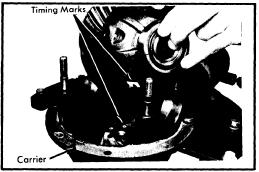
Backlash and Side Bearing Preload - 1) Place differential case assembly into carrier making sure timing marks on ring and pinion gears are aligned. Install bearing adjusters and bearing caps, then tihgten bearing cap nuts or bolts finger tight. Turn adjuster with suitable spanner wrench (49 0259 720) until bearing end play is eliminated and some backlash exists between ring gear and pinion. Slightly tighten one bearing cap nut or bolt on each side of carrier.
Fig. 8  Adjusting Differential Bearing
Preload (Case Spread)
2) Mount a dial indicator to carrier flange so button of indicator contact one of the ring gear teeth at a right angle, then check backlash between ring and pinion gears. Using the spanner wrench, turn both bearing adjusters equally until backlash is as specified in Axle Assembly Specifications.
3) Differential bearing preload (case spread) is obtained by tightening bolt bearing adjusters equally. Tighten adjusters until the distance between pilot section of side bearing caps as specified in Axle Assembly Specifications. Tighten bearing cap nuts or bolts, then recheck backlash adjustment. Make a gear tooth pattern check to insure correct assembly, then install adjuster lock plates on bearing caps.


Monday, July 2, 2012

Mazda 1968-74 Models Drive Axles Repair Manual

MODELS COVERED:

  • 616 (1971)
  • 618 (1972-73)
  • 808 (1972-74)
  • 1200 (1971-72)
  • B1600 (1972-74)
  • R100 (1971-72)
  • RX-2 (1971-74)
  • RX-3 (1972-74)
  • RX-4 (1974)
  • RE (Rotary Pick-Up) (1974)
DESCRIPTION
Axle housing is banjo type with removable differential carrier and semi-floating axle shafts. Ring and pinion are hypoid type in which centerline of pinion is set below centerline of ring gear. Differential case may be either two pinion or four pinion design. The axle shafts are retained in housing by ball bearings and bearing retainers at axle housing outer ends.
AXLE RATIO AND IDENTIFICATION
All Mazda models use one basic type of rear axle assembly. Any differences in Removal and Installation or Overhaul procedures will be noted where they occur. To determine axle ratio, divide number of ring gear teeth by number of pinion teeth.
REMOVAL AND INSTALLATION
Axle Shaft and Bearings
Removal (All. Exc. Pick-Up) - Remove wheel and tire assembly and brake drum. Remove brake shoe return springs and brake shoes. On RX-4 models, remove center cap adapter from axle shaft flange. On all models, withdraw nuts attaching retainer and backing plate to axle housing, then use a suitable puller (49 0259 631 and 49 0223 630A) to remove axle from housing.
Bearing Replacement (All Exc. Pick-Up) - Remove axle bearing and collar using a press and a suitable bearing adapter (49 0259 745). NOTE - If pressure necessary to remove bearing exceeds 10 tons, or if bearing adapter is not available, grind bearing retaining collar down and cut with a chisel to remove. To reassemble, apply a light coat of oil to axle shaft and place bearing retainer and spacer on shaft. Position bearing on shaft with sealed side toward axle shaft flange, then press bearing on shaft until spacer contacts shaft shoulder. Next, press bearing retaining collar on shaft until it seats firmly against bearing. NOTE - Do not press bearing and collar on shaft at the same time. In addition, if collar is installed with less than 3 tons of pressure, replace a new part.

AXLE SHAFT ASSEMBLY (EXCEPT PICK-UP)
Installation (All Exc. Pick-Up - 1) Apply a light coat of grease to oil seal in axle housing. Check axle shaft end clearance as follows. Install backing plate and gasket temporarily and measure depth of bearing seat in axle housing. Then measure width of axle bearing outer race. The difference between the two measurements indicates the required thickness of shim.
2) Shims are available in thicknesses of .004" (.1 mm) and .016" (.4 mm). After selecting correct shim pack, apply sealant to shims and position brake backing plate and shims on axle housing. Install axle shaft assembly in housing using a new gasket, then install and tighten retainer bolts. At this time, recheck end play, maximum end play allowable is .004" (.1 mm). Install brake shoes, return springs, brake drum and wheel and tire assembly.
AXLE SHAFT ASSEMBLY (B1600 & RE PICK-UP)
Removal (B1600 and Pick-Up) - Remove wheel and tire assembly, then remove brake drum and brake shoes. Remove parking brake cable retainer and disconnect brake lines at wheel cylinders. Remove nuts attaching backing plate and bearing housing to axle housing, then pull axle shaft, backing plate, bearing housing assembly, and shims off axle housng.
Bearing Replacement (B1600 and RE Pick-Up) - Straighten tools of lock washer, and using a suitable spanner wrench (49 0603 621A), remove lock nut and lock washer. Using a puller withdraw bearing and housing assembly from axle shaft, then remove backing plate. Remove bearing and oil seal from housing. To reassemble, reverse disassembly procedure.
Installation (B1600 and RE Pick-Up) 1) Install axle shaft, backing plate, and bearing housing to rear axle housing, temporarily attaching with two bolts and nuts. Mount a dial indicator on backing plate and check axle shaft end play. End play should be .002-.006" (.05-.15 mm).
2) NOTE - If both axle shafts were removed, a special procedure must be followed: The end play for the first axle shaft installed should be set to .026-.033" (.65-.85 mm). The second axle shaft installed should be set to the normal end play of .002-.006" (.05-.15 mm).

DIFFERENTIAL CARRIER
Removal and Installation - Raise vehicle until rear wheels are clear of ground. Remove drain plug and drain rear axle lubricant, reinstall plug and tighten. Remove axle shafts. Mark propeller shaft and pinion flange for reassembly reference, then disconnect propeller shaft. Remove carrier attaching nuts and withdraw carrier from axle housing. To install, reverse removal procedure, making sure to refill axle with lubricant.

OVERHAUL
Disassembly 
MEASURING PINION HEIGHT
1) Mount carrier in a suitable repair stand. Attach a dial indicator to carrier (with button of indicator contacting backface of ring gear) and check ring gear deflection. Maximum allowable deflection is .004" (.1 mm); replace ring and pinion if above specification. Punch identification marks on side bearing supports of carrier, differential bearing caps, and side bearing adjusters. Remove adjuster lock plates, loosen bearing cap attaching nuts or bolts, and slightly back off adjusters to relieve preload.
2) Remove bearing caps and adjusters, then withdraw differential assembly from carrier, making sure side bearing races remain with their respective bearings. If necessary for replacement, use a suitable puller and remove side bearings from gear case. Straighten lock tabs, remove ring gear attaching bolts, and separate ring gear from gear case.
3) On all models except RX-4, drive out differential pinion shaft lock pin with a punch and remove pinion shaft. Rotate pinion gears 90 degrees and remove gears, thrust washers, thrust block (if equipped), and differential side gears. On RX-4 models, remove bolts joining differential case halves and separate case. Remove side gears, thrust washers, pinion gears, and spider.
4) On all models, remove pinion nut and pinion flange. Remove drive pinion and rear bearing assembly, adjusting shims (if equipped), spacer and bearing collar if used). NOTE - It may be necessary to top end of pinion with soft hammer to remove from carrier. Remove front oil seal and withdraw front pinion bearing. Using a press, remove rear bearing from drive pinion, then lift off pinion adjusting shim. If necessary for replacement, use a drift punch and remove pinion bearing races from carrier.
MAZDA REAR AXLE ASSEMBLY

REASSEMBLY AND ADJUSTMENT
Drive Pinion Depth - 1) NOTE -The use of a suitable dial indicator assembly (49 0727 570) and pinion gauging set (49 0305 555, all exc. pick-up; or 49 0603 555A, B1600 and RE pick-up) is required for this procedure. Install dial indicator on gauge body, place gauge body on a surface plate, and preload indicator .040-.120" (1-3 mm). When preloaded, turn outer ring of indicator assembly to "zero" gauge.
2) Make sure differential bearing bores are free of dirt and burrs, then install drive pinion, dummy bearing, and original pinion depth shim into carrier. Place gauge block on pinion and position indicator assembly on block so button of indicator contacts lowest portion of differential bore.
3) Record the amount indicator moves in a "+" (plus) or "-" (minus) direction from zero. Remove gauging assembly and pinion from carrier. Check rear face of pinion for the machining correction figure. If pinion is marked "+" (plus), SUBTRACT amount specified on pinion from dial indicator reading; if marked "-" (minus), ADD amount to indicator reading. NOTE - Figures on pinion are hundredth millimeters.
4) Place dummy pinion and rear pinion bearing on surface plate and compare heights. If pinion bearings is higher than dummy bearing, SUBTRACT difference from dial indicator reading, if pinion bearing is lower than dummy bearing, ADD amount to indicator reading.
5) Select correct pinion depth adjusting shim to be used for reassembly by adding or subtracting the amount determined in steps 2), 3), and 4) from the thickness of the original pinion depth shim used during gauging process. Position correct shim on pinion and install pinion bearing. Shims are available in the following thicknesses for all models except RX-4:
Identification Mark                              Thickness In. (mm)
08.......................................................   .121 (3.08)
11.......................................................   .122 (3.11)
14.......................................................   .124 (3.14)
17.......................................................   .125 (3.17)
20.......................................................   .126 (3.20)
23.......................................................   .127 (3.23)
26.......................................................   .128 (3.26)
29.......................................................   .130 (3.29)
32.......................................................   .131 (3.32)
35.......................................................   .132 (3.35)
38.......................................................   .133 (3.38)
41.......................................................   .134 (3.41)
44.......................................................   .135 (3.44)
SOLID BEARING PRELOAD SPACER
AND SHIMS
47.......................................................   .137 (3.47)
For RX-4 models, the following thickness shims are available
Identification Mark                             Thickness In. (mm)
52.......................................................   .139 (3.52)
55.......................................................   .140 (3.55)
58.......................................................   .141 (3.58)
61.......................................................   .142 (3.61)
64.......................................................   .143 (3.64)
67.......................................................   .145 (3.67)
70.......................................................   .146 (3.70)
73.......................................................   .147 (3.73)
Pinion Bearing Preload (W/ Solid Bearing Spacer) - 1) Position drive pinion and rear bearing assembly into carrier, then install bearing spacer and preload shims onto pinion. Install front pinion bearing and pinion flange (do not install oil seal at this time). Install pinion nut and tighten to 110 ft. lbs. (15 mkg) on 1200 models or 130 ft. lbs. (18 mkg) on R-100 models.
2) Using a torque wrench installed on pinion nut, measure turning torque of drive pinion through at least one full revolution. If preload is greater than specified (see Axle Assembly Specifications), a thicker shim or longer bearing spacer is required; if preload is less than specified, a thinner shim or shorter bearing spacer is required. Shims and spacer are available in the following thicknesses and lengths:
Identification Mark                               Thickness/Length In. (mm)
INSTALLING COLLAPSIBLE
BEARING SPACER
Shims
   4.....................................................   .013 (.34)
   6.....................................................   .014 (.36)
   8.....................................................   .015 (.38)
Spacer (1200 Model Only)
   10...................................................   1.658 (41.10)
   18...................................................   1.661 (41.18)
   26...................................................   1.664 (41.26)
   34...................................................   1.668 (41.34)
Spacer (R-100 Model Only)
   60...................................................   2.149 (54.60)
   68...................................................   2.152 (54.68)
   76...................................................   2.155 (54.76)
   84...................................................   2.159 (54.84)
INSTALLING PINION SHAFT
& LOCK PIN
3) After obtaining correct preload shim pack, remove pinion flange, install pinion oil seal, and reinstall pinion oil seal, and reinstall pinion flange. Tighten pinion nut to specification.
Pinion Bearing Preload (W/Collapsible Bearing Spacer) - 1) Position drive pinion in carrier and install bearing spacer. Place front pinion bearing in position on pinion gear, hold gear fully forward, and drive bearing over pinion until seated. Apply grease to lip of pinion by tapping with a soft hammer. Install pinion washer and nut. Before tightening nut (when pinion preload is zero), check oil seal drag using a torque wrench. Tighten pinion nut as follows:
Application                                       Ft. Lbs. (mkg)
808 (W/1300 cc)...................................   87 (12)
INSTALLING DIFFERENTIAL
ASSEMBLY
RX-4....................................................  101(14)
B1600, RE (Rotary Pick-Up)...................  145(20)
All Others..............................................   94(13)
2) With nut tightened, check preload using a torque wrench mounted on pinion nut. If preload is not as specified (see Axle Assembly Specifications), continue tightening nut and checking preload until specified preload is obtained. CAUTION - Preload builds quickly. Nut should be tightened a little at a time and preload checked after each slight amount of tightening.
Case Assembly - 1) On all models except RX-4, install a thrust washer on each differential side gear and install into case. Through openings in gear case, insert pinion gears exactly 180 degrees opposite each other. Rotate pinion gears 90 degrees so holes in gears line up with pinion shaft holes in gear case. Insert pinion shaft through case and pinion gears.
ADJUSTING BEARING PRELOAD
(CASE SPREAD)
2) On RX-4 models, install a thrust washer on each differential side gear and install into case halves. Position pinion gears on spider and install spider into differential case half. Align identification marks, mate case halves, and install and tighten retaining bolts.
3) On all models, check backlash between side gears and pinion gears. Backlash should be less than .004" (.1 mm); if not, install selective thrust washers to bring backlash within specifications. Washers are available in thicknesses of .063" (1.6 mm), .067" (1.7 mm), .071" (1.8 mm), .079" (2.0 mm), .083" (2.1 mm), and .087" (2.2 mm). NOTE - Always use some thickness thrust washer for both side gears.
4) If equipped with thrust block, remove pinion shaft, install thrust block, and reinstall pinion shaft. On all models except RX-4, drive lock pin into case to secure pinion shaft. Using a punch, shake lock pin into case to secure pinion shaft. Using a punch, stake lock pin hole to prevent pin from working loose. On all models, mount ring gear on case, then install and tighten ring gear attaching bolts. If removed, instal differential side bearings.
Backlash & Side Bearing Preload - 1) Place differential case assembly into carrier making sure timing marks on ring and pinion gears are aligned. Install bearing adjusters and bearing caps, then tighten bearing cap nuts or bolts finger tight. Turn adjusters with a suitable spanner wrench (49 0259 720) until bearing end play is eliminated and some backlash exists between ring gear and pinion. Slightly tighten one bearing cap nut or bolt on each side carrier.
2) Mount a dial indicator to carrier flange so button of indicator contacts of the ring gear teeth at a right angle then check backlash between ring and pinion gears. Using the spanner wrench, turn both bearing adjusters equally until backlash is as specified in Axle Assembly Specifications.
3) Differential bearing preload (case spread) is obtained by tightening both bearing adjusters equally.  Tighten adjusters until the distance between pilot section of side bearing caps in as specified in Axle Assembly Specifications. Tighten bearing cap nuts or bolts, then recheck backlash adjustement. Make a gear tooth pattern check to insure correct assembly, then install adjuster lock plates on bearing caps.