For Toyota Models (1965-73)
CHANGES, CAUTIONS, CORRECTIONS
BATTERY INSTALLATION & OTHER ELECTRICAL SYSTEM
REPAIR CAUTIONS-Reversed polarity or excessive voltage will result in extensive damage to alternator system. Note the following to prevent damage.
Battery Installation - Negative battery terminal must be connected to ground (negative ground systems) and positive terminal must be connected to starter. DO NOT reverse battery leads.
Battery Charging - If a Quick Charger is used, both battery cables must be disconnected from battery. DO NOT use a Quick Charger to provide starting voltage.
 |
| NIPPONDENSO ALTERNATOR (TYPICAL) |
Circuit Interruption - Battery must NEVER be disconnected while alternator is running.
Alternator Removal - Always disconnect battery ground before replacement of alternator.
High Voltage - DO NOT use a high voltage source to test diodes.
Booster Battery (For Engine Start) - Booster battery must be connected with negative lead to positive battery terminal. DO NOT reverse battery leads.
DESCRIPTION
Nippondenso alternators are conventional, three-phase, self rectifying type alternators. Six diodes (three positive and three negative) are used to rectify current
APPLICATION
Model Toyota Part No.
KC (1969-70)
Corolla 1100 Before 2/69 .......................... 22010
Corolla 1100 After 2/69.............................. 22011
3K-C (1970-73)
Corolla 1200 (1970-72)............................ *22011
All Models W/ 3K-C Eng. (1973)............... 24031
2T-C (1971-72)
Corolla (1971-72)...................................... 25010
Carina (1972)........................................................
All Models W/2T-C Eng. (1973)................ 25010
BR-C (1969-71)
Corona Mk II.............................. 33010 & 33030
Hi-Lux.............................. 22011, 31031 &31032
Corona & Celica......................................... 33011
3R-B (1965-67)
1900 Sedan................................................. 21011
Corona & Crown
Before Eng. 3R 479894............................ 21010
After Eng. 3R 479894................................ 21011
Stout Pickup
Before Eng. 3R 590915............................ 40010
After Eng. 3R 590915.............................. 40011
3R-C (1968-70)
Corona & Hilux
Before 6/68.............................................. 21011
After 6/68................................................ 40060
18R-C (172-73)
Corona & Celica (1972).............................. 33011
Corona Mk II (1972).................................. 33030
Hi-Lux (1972)............................................. 31032
All 1973 BR-C Eng. ................................... 33030
M (1965-68)
Crown Before 11/68.................................... 41011
2M (1968-71)
Crown
After 11/68............................................... 41011
After 9/69................................................. 41012
4M (1971-73)
Crown (1971-72).................................... **41032
Corona (1971-72)................................. ***41032
All 4M Eng. (1973)..................................... 45020
F (1965-73)
From Eng. F224280.................................... 60021
From Eng. F243298............................**** 60031
From Eng. F270964.................................... 60040
From 1/71.........................................***** 60033
All F Eng. (1973)........................................ 60040
* - All part numbers start with 27020 prefix
** - Part number 22012 is optional.
*** - Part number 45010 is optional.
**** - Part numbers 60012, 60040 & 60022 are iotuibak,
***** - Part number 60040 is optional.
Application* Amps. **Volts
21010...........................40.....................14
21011...........................40.....................14
22010...........................25.....................14
22011.....................***25.....................14
22012...........................30.....................14
24031...........................35.....................14
25010...........................40.....................14
31031...........................30.....................14
31032...........................30.....................14
33010...........................40..........13.5-14.8
33011...........................40.....................14
33030...................****45.....................14
40010...........................40.........13.5-14.8
40011...........................40.........13.5-14.8
40060...........................40.........13.5-14.8
41010...........................40.........13.5-14.8
40011...........................40.........13.5-14.8
40012...........................40.........13.5-14.8
41032...........................45.........13.5-14.8
45010...........................55....................14
45020...........................55....................14
60012...........................35....................14
60021...........................50....................14
60022...........................50....................14
60031...........................40....................14
60032...........................40....................14
60033...........................40....................14
60040...........................55....................14
* - All part numbers start with 27020 prefix.
** - Nominal voltage, 12.
*** - Optional for part number 27020 22011 is 30 amps.
**** - Amps for part number 27020 33030 ub 1973 us 50.
Coil Resistance (Ohms)
Application Rotor Stator
21010......................3.6...............................
21011......................3.6...............................
22010......................4.2...............................
22012......................4.2...............................
24031......................4.2...............................
25010......................4.2........................0.24
31031......................4.2...............................
31032......................4.2...............................
33010......................4.2........................0.37
33011......................4.2........................0.37
33030......................4.8........................0.24
40010......................3.6...............................
40011......................3.6...............................
40060......................3.6...............................
41010..........................................................
41011......................4.2........................0.24
41012......................4.2........................0.24
41032......................4.2........................0.37
45010......................4.2........................0.37
45020......................4.2........................0.37
60012.........................................................
60021.........................................................
60022.........................................................
60031......................4.2..............................
60032.........................................................
60033......................4.2..............................
60040......................4.8..............................
* - All part numbers start with 27020 prefix.
Minimum Brush Length
Application* In. (mm)
21010, 21011, 22010................. .354 (9)
22011, 22012, 24031................. .354 (9)
40010, 40011, 40060................. .354 (9)
25010, 31031, 31032.............. .334 (8.5)
33010, 33011, 33030.............. .334 (8.5)
41010, 41011, 41012.............. .334 (8.5)
41032, 45010, 45020.............. .334 (8.5)
60012, 60021, 60022.............. .217 (5.5)
60031, 60032, 60033.............. .217 (5.5)
60040...................................... .217 (5.5)
* - All part numbers start with 27020 prefix.
Preliminary Inspection - Check alternator mounting and belt tension. Inspect turn signal fuse and gauge fuse. Check alternator and regulator wire connections for tightness
No-Load Test - 1) Connect test meters as shown in illustration. Start engine and increase speed to 2300 RPM (gradually). Read the "B" terminal voltage. It should be 13.8-14.8 volts with current draw of not more than 10 Amps. If current is over 10 Amps the battery is discharged or internally shorted.
2) If voltage reading is not steady, it indicates regulator points are dirty, or defective connection exists at "F" terminal.
3) If voltage reading is too high, it indicates the following problems: Regulator low speed gap is too wide. High speed point gap is too wide. High speed point resistance is too high. Open circuit regulator coil or
voltage relay coil. Open circuited regulator coil or voltage relay coil. Open circuited regulator "N" terminal or "B" terminal. Low speed point contact tension too heavy. Loose regulator ground connection.
"F" Terminal Voltage Test - Stop Engine, disconnect alternator wiring connector, turn ignition switch to "ON" and measure voltage between "F" and "E" terminals of connector. Voltage should be 12 volts. If voltage is zero or very low, note the following possible causes: blown fuse, regulator "IG" terminal open, or regulator high speed points are burned.
Regulator Circuit Resistance - Disconnect regulator connector plug and check resistance between regulator "IG" and "F" terminals with an ohmmeter. If there is any resistance, the low speed contact in regulator is defective.
Load Test - Connect test meter as shown in illustration. Start engine, load system by turning all lights and accessories on. Run engine at 1100 RPM. Read amperage and voltage, it should be as specified. If battery is fully charged and reading is low, discharge battery by cranking engine (without spark) for about 15 seconds. Now if amperage is low, the rectifiers are open, shorted, or stator coil is open or shorted.
1) Remove three retaining screws and insert screwdrivers into notches in drive end frame, pry with screwdrivers to separate drive end frame from stator. If necessary, tap lightly o drive end frame with a mallet.
2) Secure rotor core in padded vise, remove pulley attaching nut, and withdraw pulley, fan, and spacer. Remove rotor from drive end frame, utilizing a press. Remove bearing retainer from drive end frame, then remove bearing, felt cover and felt ring.
3) Remove four rectifier holder securing nuts and two brush holder securing screws; separate stator with rectifier holders and brush holders from rectifier end frame. Remove brush lead terminal and stator coil "N" terminal from brush holder, utilizing a small screwdriver. CAUTION - When removing brush holder assembly, do not remove it by cutting "N" terminal lead or melting the solder.
TESTING
Rotor - Check rotor for open field windings by connecting an ohmmeter across the slip rings. Coil resistance should be approximately as specified. Next check bearing and replace if necessary. Check slip rings for rough condition.
Stator - Use ohmmeter to check stator coil for ground. To check stator for open circuit, stator leads must be disconnected from diode leads. To disconnect leads from diodes, unsolder as quickly as possible and with a low-watt iron. Check four leads of stator coil for conduction, stator coil is open and must be replaced. Resistance should be zero.
Diode Test - With diode assembly on bench, make test connections as illustrated, using an ohmmeter. Contact diode plate with one probe and contact each of the three diode leads with other probe. Not ohmmeter reading, then reverse probes and repeat test. Check both positive and negative diodes in this manner. All diodes should show a low reading in one direction and no reading in opposite direction. If any one rectifier is defective, always replace positive or negative holder assembly.
PARTS REPLACEMENT
Brushes - Check for cracks and wear. If brushes are worn beyond specifications, replace. Brushes should slide smoothly. Install new brush spring when replacing brush. Solder brush lead wire keeping protruded length to .51" (13 mm).
REASSEMBLY
Reassemble alternator by reversing disassembly procedure, noting the following points:
1) Press brushes, against spring tension, into brush holder. Insert a wire through access hole in rectifier and frame, and into hole in brush holder. This will prevent brushes from falling. Remove wire after assembly to end frame is completed.
2) Pack multipurpose grease into rear beraing and press bearing onto rotor shaft.
3) Install felt ring and felt cover so that convex surface of cover will face toward pulley side onto drive end frame. Next pack multipurpose grease into bearing and install bearing.
Corolla 1200 (1970-72)............................ *22011
All Models W/ 3K-C Eng. (1973)............... 24031
2T-C (1971-72)
Corolla (1971-72)...................................... 25010
Carina (1972)........................................................
All Models W/2T-C Eng. (1973)................ 25010
BR-C (1969-71)
Corona Mk II.............................. 33010 & 33030
Hi-Lux.............................. 22011, 31031 &31032
Corona & Celica......................................... 33011
3R-B (1965-67)
1900 Sedan................................................. 21011
Corona & Crown
Before Eng. 3R 479894............................ 21010
After Eng. 3R 479894................................ 21011
Stout Pickup
Before Eng. 3R 590915............................ 40010
After Eng. 3R 590915.............................. 40011
3R-C (1968-70)
Corona & Hilux
Before 6/68.............................................. 21011
After 6/68................................................ 40060
18R-C (172-73)
Corona & Celica (1972).............................. 33011
Corona Mk II (1972).................................. 33030
Hi-Lux (1972)............................................. 31032
All 1973 BR-C Eng. ................................... 33030
M (1965-68)
Crown Before 11/68.................................... 41011
2M (1968-71)
Crown
After 11/68............................................... 41011
After 9/69................................................. 41012
4M (1971-73)
Crown (1971-72).................................... **41032
Corona (1971-72)................................. ***41032
All 4M Eng. (1973)..................................... 45020
F (1965-73)
From Eng. F224280.................................... 60021
From Eng. F243298............................**** 60031
From Eng. F270964.................................... 60040
From 1/71.........................................***** 60033
All F Eng. (1973)........................................ 60040
* - All part numbers start with 27020 prefix
** - Part number 22012 is optional.
*** - Part number 45010 is optional.
**** - Part numbers 60012, 60040 & 60022 are iotuibak,
***** - Part number 60040 is optional.
SPECIFICATIONS
Rated Output @ 3500 RPMApplication* Amps. **Volts
21010...........................40.....................14
21011...........................40.....................14
22010...........................25.....................14
22011.....................***25.....................14
22012...........................30.....................14
24031...........................35.....................14
25010...........................40.....................14
31031...........................30.....................14
31032...........................30.....................14
33010...........................40..........13.5-14.8
33011...........................40.....................14
33030...................****45.....................14
40010...........................40.........13.5-14.8
40011...........................40.........13.5-14.8
40060...........................40.........13.5-14.8
41010...........................40.........13.5-14.8
40011...........................40.........13.5-14.8
40012...........................40.........13.5-14.8
41032...........................45.........13.5-14.8
45010...........................55....................14
45020...........................55....................14
60012...........................35....................14
60021...........................50....................14
60022...........................50....................14
60031...........................40....................14
60032...........................40....................14
60033...........................40....................14
60040...........................55....................14
* - All part numbers start with 27020 prefix.
** - Nominal voltage, 12.
*** - Optional for part number 27020 22011 is 30 amps.
**** - Amps for part number 27020 33030 ub 1973 us 50.
Coil Resistance (Ohms)
Application Rotor Stator
21010......................3.6...............................
21011......................3.6...............................
22010......................4.2...............................
22012......................4.2...............................
24031......................4.2...............................
25010......................4.2........................0.24
31031......................4.2...............................
31032......................4.2...............................
33010......................4.2........................0.37
33011......................4.2........................0.37
33030......................4.8........................0.24
40010......................3.6...............................
40011......................3.6...............................
40060......................3.6...............................
41010..........................................................
41011......................4.2........................0.24
41012......................4.2........................0.24
41032......................4.2........................0.37
45010......................4.2........................0.37
45020......................4.2........................0.37
60012.........................................................
60021.........................................................
60022.........................................................
60031......................4.2..............................
60032.........................................................
60033......................4.2..............................
60040......................4.8..............................
* - All part numbers start with 27020 prefix.
Minimum Brush Length
Application* In. (mm)
21010, 21011, 22010................. .354 (9)
22011, 22012, 24031................. .354 (9)
40010, 40011, 40060................. .354 (9)
25010, 31031, 31032.............. .334 (8.5)
33010, 33011, 33030.............. .334 (8.5)
41010, 41011, 41012.............. .334 (8.5)
41032, 45010, 45020.............. .334 (8.5)
60012, 60021, 60022.............. .217 (5.5)
60031, 60032, 60033.............. .217 (5.5)
60040...................................... .217 (5.5)
* - All part numbers start with 27020 prefix.
TESTING
ON CAR TEST |
| TEST CIRCUIT FOR LOAD TEST |
Preliminary Inspection - Check alternator mounting and belt tension. Inspect turn signal fuse and gauge fuse. Check alternator and regulator wire connections for tightness
No-Load Test - 1) Connect test meters as shown in illustration. Start engine and increase speed to 2300 RPM (gradually). Read the "B" terminal voltage. It should be 13.8-14.8 volts with current draw of not more than 10 Amps. If current is over 10 Amps the battery is discharged or internally shorted.
2) If voltage reading is not steady, it indicates regulator points are dirty, or defective connection exists at "F" terminal.
3) If voltage reading is too high, it indicates the following problems: Regulator low speed gap is too wide. High speed point gap is too wide. High speed point resistance is too high. Open circuit regulator coil or
 |
| CHECKING VOLTAGE BETWEEN "F" & "E" TERMINALS |
"F" Terminal Voltage Test - Stop Engine, disconnect alternator wiring connector, turn ignition switch to "ON" and measure voltage between "F" and "E" terminals of connector. Voltage should be 12 volts. If voltage is zero or very low, note the following possible causes: blown fuse, regulator "IG" terminal open, or regulator high speed points are burned.
Regulator Circuit Resistance - Disconnect regulator connector plug and check resistance between regulator "IG" and "F" terminals with an ohmmeter. If there is any resistance, the low speed contact in regulator is defective.
Load Test - Connect test meter as shown in illustration. Start engine, load system by turning all lights and accessories on. Run engine at 1100 RPM. Read amperage and voltage, it should be as specified. If battery is fully charged and reading is low, discharge battery by cranking engine (without spark) for about 15 seconds. Now if amperage is low, the rectifiers are open, shorted, or stator coil is open or shorted.
OVERHAUL
DISASSEMBLY |
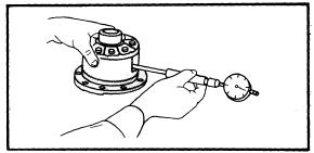
| TESTING DIODES |
1) Remove three retaining screws and insert screwdrivers into notches in drive end frame, pry with screwdrivers to separate drive end frame from stator. If necessary, tap lightly o drive end frame with a mallet.
2) Secure rotor core in padded vise, remove pulley attaching nut, and withdraw pulley, fan, and spacer. Remove rotor from drive end frame, utilizing a press. Remove bearing retainer from drive end frame, then remove bearing, felt cover and felt ring.
3) Remove four rectifier holder securing nuts and two brush holder securing screws; separate stator with rectifier holders and brush holders from rectifier end frame. Remove brush lead terminal and stator coil "N" terminal from brush holder, utilizing a small screwdriver. CAUTION - When removing brush holder assembly, do not remove it by cutting "N" terminal lead or melting the solder.
TESTING
Rotor - Check rotor for open field windings by connecting an ohmmeter across the slip rings. Coil resistance should be approximately as specified. Next check bearing and replace if necessary. Check slip rings for rough condition.
 |
| ALTERNATOR GENERATING CIRCUIT (WITH VOLTAGE RELAY) |
Diode Test - With diode assembly on bench, make test connections as illustrated, using an ohmmeter. Contact diode plate with one probe and contact each of the three diode leads with other probe. Not ohmmeter reading, then reverse probes and repeat test. Check both positive and negative diodes in this manner. All diodes should show a low reading in one direction and no reading in opposite direction. If any one rectifier is defective, always replace positive or negative holder assembly.
PARTS REPLACEMENT
 |
| ALTERNATOR GENERATING CIRCUIT (WITHOUT VOLTAGE RELAY) |
Brushes - Check for cracks and wear. If brushes are worn beyond specifications, replace. Brushes should slide smoothly. Install new brush spring when replacing brush. Solder brush lead wire keeping protruded length to .51" (13 mm).
REASSEMBLY
Reassemble alternator by reversing disassembly procedure, noting the following points:
1) Press brushes, against spring tension, into brush holder. Insert a wire through access hole in rectifier and frame, and into hole in brush holder. This will prevent brushes from falling. Remove wire after assembly to end frame is completed.
2) Pack multipurpose grease into rear beraing and press bearing onto rotor shaft.
3) Install felt ring and felt cover so that convex surface of cover will face toward pulley side onto drive end frame. Next pack multipurpose grease into bearing and install bearing.