Cricket (1971 to 72) Repair Manual
DESCRIPTION
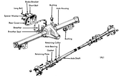
Axle assembly is a semi-floating type with integral carrier. Drive pinion is carried on two taper roller bearings adjusted to a preload condition by use of collapsible spacer. A one piece differential case with a hypoid gear assembly is carried in axle housing on adjustable taper roller bearings, secured by caps and bolts. Ring gear-to-pinion mesh is controlled by screw adjusters which are locked in position with lock plates. Steel thrust washers are used between differential gears and case. Axles are carried by sealed ball bearing which are retained by pressed-on collars. No drain plug is provided, if necessary, oil is drained by removing rear cover
AXLE RATIO AND IDENTIFICATION
Both manual and automatic transmission models have an axle ratio of 3.889-1. There are 35 teeth on the ring gear and nine teeth on the pinion gear.
 |
| CRICKET REAR AXLE ASSEMBLY |
REMOVAL AND INSTALLATION
AXLE SHAFTS AND BEARINGS
 |
| CHECKING BEARING PRELOAD |
2) Remove four self-locking nuts attaching axle shaft retaining plate. Using suitable slide hammer (S-93 & C-637), remove axle shaft and bearing form axle housing. NOTE - Do not pry axle shaft out against brake support plate or plate may be distorted.
3) Using a suitable arbor press and tool (C-3926), press bearing and retaining collar from axle.
Installation - 1) With axle retainer plate positioned on axle with swaged center towards axle flange, press collar and bearing onto axle until extended boss of bearing is fully seated against axle face. NOTE - A minimum ram load of 3000 lbs. (1361 kgs.) is required for a correct fit. Otherwise it will be necessary to install a replacement axle.
2) Slide axle shaft into housing and align splines with those in differential side gear. Push shaft in and enter bearing into recess in axle housing.
3) Position retaining plate over four studs and tighten self-locking nuts. NOTE - Do not use retaining plate to draw bearing and axle shaft into position or excessive axle shaft end play will result.
 |
| CRICKET DIFFERENTIAL ASSEMBLY |
PINION FLANGE AND SEAL
Removal - 1) Jack up rear of vehicle and support on floor stands. Scribe mark propeller shaft and pinion flanges for correct reassembly. Remove attaching bolts and tie propeller shaft aside. Wrap a card around flange and attach a spring scale to determine amount of preload poundage required to rotate flange. Note poundage for reassembly.
2) Scribe mark flange and pinion shaft for reaasembly. Using a suitable tool (C-3281) to hold flange, remove flange nut and flange. Drive one side of seal inward as far as it will go. Grasp other side of seal and pull from housing.
Installation - 1) Coat internal flange with grease and place seal lip facing housing. Using suitable tool (C-3837), drive oil seal into housing until tool contacts housing.
2) Install flange to previous marks. Install a new pinion nut (being careful not to overtighten) and tighten until pinion end play just disappears. Rotate pinion to seat bearings.
3) Progressively tighten nut a very small amount at a time, rotate pinion and measure preload. Continue this procedure until previously noted preload is restored. CAUTION - Recorded preload must not be exceeded. If preload is exceeded, remove differential assembly and install a new collapsible spacer.
AXLE ASSEMBLY
Removal - 1) Raise rear of vehicle and place floor stands under rear body jacking points. Using care not to damage housing cover, jack up rear axle enough to remove rear wheels. Block brake pedal in the up position with a wooden block.
2) Disconnect shock absorbers at lower mounts. On station wagons, disconnect Panhard rod at axle. Scribe mark axle flange and propeller shaft for correct reassembly. Disconnect propeller shaft and tie aside.
| CHECKING DIFFERENTIAL GEAR CLEARANCE |
Installation - To install, reverse removal procedure. Final tightening of suspension components is done with vehicle setting on its wheels. Bleed hydraulic brake system and fill rear axle to proper level with suitable lubricant.
OVERHAUL
DISASSEMBLY
1) Remove rear cover and drain oil. Remove rear axles and bearings. See Axle Shafts and Bearings. Disconnect parking brake rod and hydraulic lines to remove brake support plates.
2) Mark differential bearing caps for reassembly to original locations. Remove locking plates, bolts and bearing caps. Remove two adjuster nuts at same time lifting out ring gear assembly and outer bearing cones.
3) Scribe mark pinion shaft and flange for reassembly. Using suitable tool (C-3281) to hold flange, remove self-locking nut and flange. With a soft mallet, gently tap pinion shaft out rear of axle housing. Using suitable tools (C-293-P and RGM-4221A-34), remove inner bearing from pinion, retaining shims for reassembly. Remove outer bearing from housing and drive bearing and seal from housing using a brass drift.
NOTE - If bearing and comes are to be reused they should be marked so that they will remain mated and return to their original positions.
4) Using suitable tools (C-293-10 and SP3183), remove bearings from differential case if necessary. Mark ring gear and differential case for reassembly. Remove eight bolts and ring gear. NOTE - Ring gear bolts are discarded and new bolts used for reassembly. Bolts are of special design and require no locking devices.
5) Drive out locking pin retaining the cross pin. Push out crosspin and rotate pinion gear 90 degrees to case openings. Lift out pinion gears and thrust washers. Side gears and washers can now be removed.
NOTE - If gear replacement is necessary, a complete set of matched gears including cross pin and locking pin will be required.
REASSEMBLY AND ADJUSTMENT
Case Assembly - 1) Install thrust washers on differential side gears and position gears in differential case. Place thrust washers on pinion gears and position gears in case in such a manner that they are 180 degrees apart when they are in mesh with side gears.
2) Rotate side gears until holes in pinion gears are in alignment with cross pin holes in case. Install cross pin and locking pin. Then push side ear on cage side (opposite ring gear) against pinions until all gear end play is removed. Measure clearance between thrust washers and side gear clearance should not exceed .010" (.25 mm).
3) Peen over locking pin hole to retain pin. Inspect ring gear and case for burrs. Install ring gear on case with marks aligned. Install a new set of bolts and tighten evenly.
Drive Pinion Depth - 1) Using suitable differential assembly jig (RG.545), pinion depth is determined with a dummy pinion shaft and mandrel. Shims to space pinion depth in differential case are available in .003" (.08 mm), .005" (.13 mm), .10" (.25 mm) and .020" (50 mm) sizes.
2) Lightly oil inner pinion bearing and place it on pinion shaft. Slide pinion shaft into housing and install outer bearing spacer and nut (do not install oil seal at this time). Tighten nut by hand until end play is removed. Rotate pinion shaft to seat bearings and continue to tighten until nut cannot be tightened further by hand. A slight drag should be felt.
3) Place mandrel in differential case and install bearings caps, torquing bolts to 15 ft. lbs. (2.1 mkg). Measure clearance between dummy pinion and mandrel with a feeler gauge. Measurement will be the actual thickness of shims required between real pinion shaft and bearing. Remove dummy pinion and mandrel. Place shims on pinion shaft and press on inner bearing until they are fully seated.
Pinion Bearing Preload - 1) Place collapsible spacer on pinion shaft and install in differential housing. Install outer bearing and oil seal. Install pinion flange and a new self-locking nut making sure marks are aligned.
2) Using suitable tool (C-3281) to hold flange, tighten nut until end play just disappears. Rotate pinion shaft to seat bearings. Wrap a cord around flange and attach a spring scale. Note reading while maintaining a steady pull. Progressively tighten nut a small amount at a time and measure preload until desired poundage is achieved. Preload for original bearings is 6-11 lbs. (2.7-5 kg) or new bearings is 8-15 lbs. (3.5-6.8 kg). Make a note of figure obtained for late calculation.
CAUTION - Do not back off nut to lessen preload. If desired preload is exceeded, a new collapsible spacer MUST be installed and nut retightened until proper preload is obtained