DESCRIPTION
Axle housing is banjo type with removable differential carrier and semi-floating axle shafts. Ring and pinion gears are hypoid type in which centerline of pinion is set below centerline of ring gear. Differential case is a one piece, two-pinion design. The axle shafts are retained in housing by cone type roller bearings and bearing retainers at axle housing outer ends.
AXLE RATIO AND IDENTIFICATION
All LUV models are equipped with one type of rear axle assembly. To determine axle ratio, divide the number of ring gear teeth by the number of drive pinion gear teeth.
 |
| Fig. 1 Exploded View of LUV Rear Axle Assembly |
REMOVAL AND INSTALLATION
Axle Shafts and Bearings
 |
| Fig. 2 Exploded View of Axle Shaft Assembly |
Bearing Replacement - 1) Flatten locking tab of lock washer, then mount axle shaft in a vise, clamping vise jaws around lock nut. Using suitable tool (J-24246) positioned on lub bolts, turn axle shaft loose from lock nut, Mount axle assembly in a press and remove lock nut, lock washer, bearing and holder, and brake backing plate. Remove oil seal from outboard side of bearing holder, then drive off bearing outer race with a drift.
2) To reassemble, install bearing outer race and grease seal into bearing holder using suitable drivers. Apply wheel bearing grease to bearing holder, rear axle tube, and bearing inner race. Insert the four through bolts into backing plate, then install bearing holder to backing plate, making sure oil seal plate assembly over axle shaft, position bearing over axle shaft and press into bearing holder. Install new lock washer with dished side away from bearing, and thread lock nut onto shaft. Place lock nut between vise jaws, and using tool used during disassembly, tighten lock nut securely. Bend over portion of lock washer opposite to locating tab to prevent lock nut from turning.
 |
| Fig. 3 Sectional View of Axle Shaft Bearing Assembly Measurement for Axle Shaft Shim Requirements |
2) Proper size shim for this location may be determined by adding .004" (.1mm) to measurement just obtained. Select a shim or combination of shims, withdraw axle shaft, and install shims between bearing holder and flange face. Reinstall axle shaft and tighten four through bolts. Connect brake line to wheel cylinder, then install brake shoes, parking brake cable, and brake drum. Install wheel and tire assembly, adjust brakes and bleed system.
DIFFERENTIAL CARRIER
Removal and Installation - Raise rear of vehicle, remove wheels and brake drums, and disconnect brake lines of rear wheel cylinders. Disconnect parking brake cable brackets at rear spring location, remove four through bolts from each and flange, and partially withdraw axle shafts from axle tubes. Disconnect propeller shaft from pinion flange and place out of way. Remove nuts attaching carrier to axle housing and remove carrier assembly. To install, reverse removal procedure, making sure to refill axle with lubricant.
OVERHAUL
Disassembly
 |
| Fig. 4 Removing Pinion Shaft Lock Pin |
Record thickness of each side bearing and each shim pack then place with appropriate bearing race
2) Remove ring gear bolts and separate ring gear from case. Drive out pinion shaft lock pin using a long drift. NOTE - It may be necessary to remove caulking in lock pin using a 5 mm drill. Remove pinion shaft using a drift, then withdraw thrust block, pinion gears, and thrust washers.
3) Remove pinion nut and pinion flange. Drive the pinion gear from carrier using a soft hammer or drift. Withdraw front pinion bearing and oil seal. Using a drift, remove pinion bearing races from carrier. Mount pinion gear in a press and remove rear pinion bearing and depth shim from pinion gear.
REASSEMBLY AND ADJUSTMENT
 |
| Fig. 5 Tool Arrangement for Measuring Drive Pinion Installed Height |
2) Place mounting discs (J-23597-8) onto arbor tool (J-23597-1) and place assembly in position in side bearing bores. Install bearing caps. Mount a dial indicator on arbor post, preload dial 1/2 revolution, then tighten indicator in this position. Position indicator plunger on gauge plate, slowly swing across until highest reading is obtained, then "zero" indicator on highest reading of gauge plate. Swing plunger off gauge plate and note indicator reading. Reading is the correct thickness of rear opinion bearing depth shim for a nominal drive pinion. NOTE - Shims are available in sizes from .086" to .101". An indicator reading of .000" or .001" requires shims of .100" and .101" respectively.
 |
| Fig. 6 Location of Pinion Depth Code on Head of Drive Pinion |
Pinion Depth Shim Chart
Pinion Code Correction Required
+10............................................. Subtract .003" (.13 mm)
+8............................................... Subtract .004" (.10 mm)
+6............................................... Subtract .003" (.08 mm)
+4............................................... Subtract .002" (.05 mm)
+2............................................... Subtract .001" (.03 mm)
0................................................. No Correction Required
-2................................................ Add .001" (.03 mm)
-4................................................ Add .002" (.05 mm)
-6................................................ Add .003" (.08 mm)
-8................................................ Add .004" (.10 mm)
-10.............................................. Add .005" (.13 mm)
 |
| Fig. 7 Using Pull Scale to Measure Drive Pinion Bearing Preload |
Pinion Bearing Preload (W/ Collapsible Bearing Spacer) - 1) Place drive pinion and collapsible spacer into carrier, then install front pinion bearing and oil seal. Mount pinion flange on drive pinion, apply lubricant to pinion threads, install pinion nut and tighten to 85 ft. lbs. (11.3 mkg). Rotate pinion to insure bearings are seated, then wind a small amount of string (approximately 4-6 windings) around pinion flange. Using a pull scale, note reading required to rotate flange.
2) Continue tightening nut in small increments until pull required to rotate flange is 17 lbs. (7.7 kg) for new bearings or 7-9 lbs. (3.2-4.1 kg) for reused bearings. CAUTION - Preload builds quickly. Nut should be tightened only in small increments and pull scale used after each small amount of tightening. If preload is exceeded, a new collapsible bearing spacer must be installed.
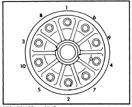 |
| Fig. 8 Ring Gear Bolt Tightening Sequence |
 |
| Fig. 9 Checking Ring Gear Backface Runout |
3) Proper preload is established using the predetermined dimension of .002". Therefore, ADD this dimension to clearance obtained in step 2) for proper preload. This will give required total thickness of both shim packs. Equally divide the total dimension required shim pack thickness for each side.
4) Remove case from carrier, remove side bearings and install shim packs, then reinstall bearings. Install differential case into carrier, tapping carefully into place. Install side bearing caps in original positions, install and tighten attaching bolts. Measure run-out of ring gear (see illustration). If run-out exceeds .002" (.05 mm), correct by clearing or replacement of parts.
5) Mount a dial indicator against ring gear teeth and measure backlash in three locations. Backlash should be .005-.007 (.13-.18 mm); if not, shims behind side bearings must be adjusted. NOTE - To maintain preload when backlash is adjusted, the total thickness of both shim packs must not be altered. Therefore, if it is necessary to increase one shim pack, the opposite shim pack must be decreased. To decrease backlash, right side shim must be decreased, and left side increased. NOTE - Backlash changes approximately .002" (.05 mm) for each .003" (.08 mm) shim change. After adjustment, make a gear tooth pattern check to insure correct assembly.

 |
| Fig. 10 Checking Ring Gear-to-Drive Pinion Gear Backlash |
5) Mount a dial indicator against ring gear teeth and measure backlash in three locations. Backlash should be .005-.007 (.13-.18 mm); if not, shims behind side bearings must be adjusted. NOTE - To maintain preload when backlash is adjusted, the total thickness of both shim packs must not be altered. Therefore, if it is necessary to increase one shim pack, the opposite shim pack must be decreased. To decrease backlash, right side shim must be decreased, and left side increased. NOTE - Backlash changes approximately .002" (.05 mm) for each .003" (.08 mm) shim change. After adjustment, make a gear tooth pattern check to insure correct assembly.
