DESCRIPTION
Brake system is hydraulically operated, using a tandem master cylinder and a Master-Vac power brake unit. Front brakes are Girling-Sumitomo dual piston fixed caliper disc type, and rear brakes are leading-trailing shoe/drum type. Brake system is equipped with a proportioning valve to prevent premature locking of rear wheels. Parking brakes is mechanically actuated, operating sliding wheel cylinders of wheel cylinders of rear brake assemblies.
Loosen lock nut, turn push rod clevis, and adjust push rod length so that height of pedal, measured from pedal pad to floor, is 8.11" NOTE - Make sure pedal stop bolt does not contact pedal arm at this time. With push rod adjusted, adjust pedal stop bolt so that pedal height is reduced from 8.11" to 7.99"
FRONT DISC BRAKE PADS
Front disc brakes are self-adjusting, therefore, no adjustment in service is required.
REAR DRUM BRAKE SHOES
Rear drum brake are self-adjusting (actuated by parking brake), therefore, no adjustment in service is required.
PARKING BRAKE
With parking brake lever fully released, make sure distance between wheel cylinder lever pin hole center and buffer plate on brake assembly backing plate is .453 - .492". Reduce play in linkage by turning adjusting nut on front parking brake operating rod.
Removal - Remove tire and wheel. Remove clip, retaining pin, damper spring and remove pad with shim.
Installation - Depress piston into cylinder so new pad may be inserted. Install pad, shim, damper spring and retaining pin securing with clip. Depress pedal several times to position new pads.
FRONT DISC BRAKE CALIPER
Removal - With disc pads removed, disconnect hydraulic line from caliper and plug openings. Remove caliper mounting bolts and separate caliper from steering knuckle and rotor.
Installation - Reverse removal procedure, tighten caliper mounting bolts securely, and bleed hydraulic system.
FRONT DISC BRAKE ROTOR
Removal - With caliper assembly removed, remove wheel hub dust cap, cotter pin, and adjusting nut. Remove wheel hub and rotor assembly, wheel bearing, and washer from spindle as an assembly. Remove bolts attaching rotor to wheel hub, and detach rotor.
Installation - Reverse removal procedure and adjust front wheel bearings.
REAR BRAKE SHOES
Removal - Remove tire, wheel and drum. NOTE - Should drum be difficult to remove: Remove clevis pin from wheel cylinder lever and disconnect handbrake cable. Remove backing plate rubber boot and loosen brake shoes, (adjust star-downward). Some difficulty may be incurred due to adjuster lever. Remove return springs, mounting springs, clips and pins.
Installation - Apply brake grease (or equivalent) to adjuster and all pivot points on backing plate. Install brake shoe return springs and mounting springs, clips, and pins. Install brake drum and adjust brakes until they just contact drum. Reconnect handbrake cable and insert rubber backing plate boot.
REAR BRAKE WHEEL CYLINDER
Removal - With rear brake shoes removed, remove hydraulic line and dust cover. Drive out lock plate toward front of vehicle, withdraw plate rearward, and remove wheel cylinder from backing plate.
Installation - Reverse removal procedure and note the following: Apply brake grease (or equivalent) to wheel cylinder, backing plate, and adjusting plate sliding surfaces; also lubricate wheel cylinder lever fulcrum and ensure wheel cylinder assembly operates freely.
MASTER CYLINDER
Removal - Disconnect hydraulic lines from master cylinder, remove nuts attaching cylinder to power unit, and separate master cylinder from power brake unit.
Installation - Reverse removal procedure, adjust brake pedal height, and bleed hydraulic system.
POWER BRAKE UNIT
Removal - Disconnect power unit push rod from brake pedal by removing clevis pin. Disconnect hydraulic lines from master cylinder, vacuum line from power unit, remove master cylinder mounting nuts, and remove master cylinder. Remove nuts attaching power unit to firewall, and remove power unit from engine compartment.
Installation - Reverse removal procedure, adjust brake pedal height, and bleed hydraulic system.
Check Valve Replacement - Check valve is located in vacuum line between intake manifold and power unit on firewall. To remove, disconnect retaining clip from firewall, remove hose clamps, separate hoses from valve, and remove check valve. To install, reverse removal procedure.
Disassembly - Clean exterior of brake caliper. Remove retaining ring and dust seal. Using a small block of wood, (or equivalent), hold one piston and blow air into brake line inlet to force piston from bore. Remove piston seal fro cylinder bore. Remove other piston in similar manner.
Cleaning & Inspection - Clean al parts in alcohol or brake fluid. CAUTION - DO NOT use mineral based solvents. Inspect caliper bores for wear, rust, corrosion, or other damage; minor deposits or scratches may be removed with fine emery cloth. Check piston for wear or damage. NOTE - DO NOT use abrasives on piston plated surfaces.
Reassembly - NOTE - Manufacturer recommends replacing rubber parts whenever caliper is being overhauled. Coat piston seal with rubber grease and install into caliper bore. Install dust seal on piston, insert piston into caliper, and install retaining ring. Install opposite piston assembly in same manner.
REAR WHEEL CYLINDER
Disassembly - Remove snap ring and dust cover. Withdraw piston and seal assembly, adjuster wheel, adjuster screw, and spring.
Cleaning & Inspection - Clean all parts in alcohol or brake fluid. CAUTION - DO NOT use mineral based solvents. Check all parts for wear or damage; replace parts as necessary. Check clearance between cylinder bore and piston if clearance exceeds .006", replace cylinder or piston as necessary Check spring for damage or distortion. NOTE - Manufacturer recommends replacing seal whenever wheel cylinder has been disassembled.
Reassembly - Reverse removal procedure and note the following: Apply rubber grease to all parts when reassembling to prevent damage.
MASTER CYLINDER
Disassembly - Remove reservoir filler caps, drain brake fluid, and remove secondary piston stop bolt. Remove snap ring and withdraw primary piston, secondary piston and return springs. Remove valve caps and withdraw check valve assemblies. NOTE - Do not remove reservoirs unless necessary.

Cleaning & Inspection - Clean all parts in alcohol or brake fluid and inspect for wear or damage. Check clearance between cylinder bore and pistons; if clearance exceeds .006", replace cylinder or pistons as necessary. NOTE - Manufacturer recommends replacing piston cups, gaskets, and valves whenever master cylinder has been disassembled.
Reassembly - Reverse disassembly procedure and note the following: Apply rubber grease to all rubber parts and brake fluid to remaining parts when assembling to prevent damage.

ADJUSTMENT
BRAKE PEDALLoosen lock nut, turn push rod clevis, and adjust push rod length so that height of pedal, measured from pedal pad to floor, is 8.11" NOTE - Make sure pedal stop bolt does not contact pedal arm at this time. With push rod adjusted, adjust pedal stop bolt so that pedal height is reduced from 8.11" to 7.99"
FRONT DISC BRAKE PADS
Front disc brakes are self-adjusting, therefore, no adjustment in service is required.
REAR DRUM BRAKE SHOES
Rear drum brake are self-adjusting (actuated by parking brake), therefore, no adjustment in service is required.
PARKING BRAKE
With parking brake lever fully released, make sure distance between wheel cylinder lever pin hole center and buffer plate on brake assembly backing plate is .453 - .492". Reduce play in linkage by turning adjusting nut on front parking brake operating rod.
REMOVAL & INSTALLATION
FRONT DISC BRAKE PADSRemoval - Remove tire and wheel. Remove clip, retaining pin, damper spring and remove pad with shim.
Installation - Depress piston into cylinder so new pad may be inserted. Install pad, shim, damper spring and retaining pin securing with clip. Depress pedal several times to position new pads.
FRONT DISC BRAKE CALIPER
Removal - With disc pads removed, disconnect hydraulic line from caliper and plug openings. Remove caliper mounting bolts and separate caliper from steering knuckle and rotor.
Installation - Reverse removal procedure, tighten caliper mounting bolts securely, and bleed hydraulic system.
FRONT DISC BRAKE ROTOR
 |
| REAR BRAKE ASSEMBLY |
Removal - With caliper assembly removed, remove wheel hub dust cap, cotter pin, and adjusting nut. Remove wheel hub and rotor assembly, wheel bearing, and washer from spindle as an assembly. Remove bolts attaching rotor to wheel hub, and detach rotor.
Installation - Reverse removal procedure and adjust front wheel bearings.
REAR BRAKE SHOES
Removal - Remove tire, wheel and drum. NOTE - Should drum be difficult to remove: Remove clevis pin from wheel cylinder lever and disconnect handbrake cable. Remove backing plate rubber boot and loosen brake shoes, (adjust star-downward). Some difficulty may be incurred due to adjuster lever. Remove return springs, mounting springs, clips and pins.
Installation - Apply brake grease (or equivalent) to adjuster and all pivot points on backing plate. Install brake shoe return springs and mounting springs, clips, and pins. Install brake drum and adjust brakes until they just contact drum. Reconnect handbrake cable and insert rubber backing plate boot.
REAR BRAKE WHEEL CYLINDER
Removal - With rear brake shoes removed, remove hydraulic line and dust cover. Drive out lock plate toward front of vehicle, withdraw plate rearward, and remove wheel cylinder from backing plate.
Installation - Reverse removal procedure and note the following: Apply brake grease (or equivalent) to wheel cylinder, backing plate, and adjusting plate sliding surfaces; also lubricate wheel cylinder lever fulcrum and ensure wheel cylinder assembly operates freely.
 |
| MASTER CYLINDER ASSEMBLY |
Removal - Disconnect hydraulic lines from master cylinder, remove nuts attaching cylinder to power unit, and separate master cylinder from power brake unit.
Installation - Reverse removal procedure, adjust brake pedal height, and bleed hydraulic system.
POWER BRAKE UNIT
Removal - Disconnect power unit push rod from brake pedal by removing clevis pin. Disconnect hydraulic lines from master cylinder, vacuum line from power unit, remove master cylinder mounting nuts, and remove master cylinder. Remove nuts attaching power unit to firewall, and remove power unit from engine compartment.
Installation - Reverse removal procedure, adjust brake pedal height, and bleed hydraulic system.
Check Valve Replacement - Check valve is located in vacuum line between intake manifold and power unit on firewall. To remove, disconnect retaining clip from firewall, remove hose clamps, separate hoses from valve, and remove check valve. To install, reverse removal procedure.
OVERHAUL
FRONT DISC BRAKE CALIPER |
| FRONT BRAKE ASSEMBLY |
Disassembly - Clean exterior of brake caliper. Remove retaining ring and dust seal. Using a small block of wood, (or equivalent), hold one piston and blow air into brake line inlet to force piston from bore. Remove piston seal fro cylinder bore. Remove other piston in similar manner.
Cleaning & Inspection - Clean al parts in alcohol or brake fluid. CAUTION - DO NOT use mineral based solvents. Inspect caliper bores for wear, rust, corrosion, or other damage; minor deposits or scratches may be removed with fine emery cloth. Check piston for wear or damage. NOTE - DO NOT use abrasives on piston plated surfaces.
Reassembly - NOTE - Manufacturer recommends replacing rubber parts whenever caliper is being overhauled. Coat piston seal with rubber grease and install into caliper bore. Install dust seal on piston, insert piston into caliper, and install retaining ring. Install opposite piston assembly in same manner.
REAR WHEEL CYLINDER
 |
| REAR WHEEL CYLINDER ASSEMBLY |
Disassembly - Remove snap ring and dust cover. Withdraw piston and seal assembly, adjuster wheel, adjuster screw, and spring.
Cleaning & Inspection - Clean all parts in alcohol or brake fluid. CAUTION - DO NOT use mineral based solvents. Check all parts for wear or damage; replace parts as necessary. Check clearance between cylinder bore and piston if clearance exceeds .006", replace cylinder or piston as necessary Check spring for damage or distortion. NOTE - Manufacturer recommends replacing seal whenever wheel cylinder has been disassembled.
Reassembly - Reverse removal procedure and note the following: Apply rubber grease to all parts when reassembling to prevent damage.
MASTER CYLINDER
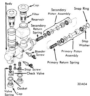
Disassembly - Remove reservoir filler caps, drain brake fluid, and remove secondary piston stop bolt. Remove snap ring and withdraw primary piston, secondary piston and return springs. Remove valve caps and withdraw check valve assemblies. NOTE - Do not remove reservoirs unless necessary.
Cleaning & Inspection - Clean all parts in alcohol or brake fluid and inspect for wear or damage. Check clearance between cylinder bore and pistons; if clearance exceeds .006", replace cylinder or pistons as necessary. NOTE - Manufacturer recommends replacing piston cups, gaskets, and valves whenever master cylinder has been disassembled.
Reassembly - Reverse disassembly procedure and note the following: Apply rubber grease to all rubber parts and brake fluid to remaining parts when assembling to prevent damage.
