DESCRIPTION
Courier dual brake system consists of a dual master cylinder, combination valve, system failure warning light, two single piston hydraulic cylinders (front wheels) and two dual piston hydraulic cylinders (rear wheels). All lines are connected to both master cylinder and combination valve. Both front and rear brakes operate same (pressurized brake fluid forced to wheel cylinder). Front cylinders however, expand each shoe individually and rear dual piston cylinders expand both shoes equally.
ADJUSTMENT
PEDAL FREE PLAY
 |
| Fig. 1 Front Brake Assembly Exploded View |
Loosen lock nut on master cylinder push rod at clevis. Turn push rod in or out to obtain .12-34" (3.0-8.6 mm) free play, measured at pedal pad. When clearance is obtained, tighten lock nut.
BRAKE SHOES
All shoe to drum adjustments must be made with brake shoes at normal room temperature. Turn lower wheel cylinder ratchet to expand brake shoe locking it against drum. Back-off ratchet 5 notches or until drum rotates freely. Repeat procedure for upper wheel cylinder.
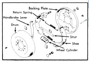 |
| Fig. 2 Rear Brake Assembly Exploded View |
PARKING BRAKE CABLE
NOTE - Service brakes must be properly adjusted before adjusting parking brake. Adjust length of cable at equalizer so that rear brakes are locked when parking brakes lever is pulled out five to ten ratchet clicks (1 5/8-3 1/2"). After adjustment, apply and release parking brake several times, and make sure wheels rotate freely when parking brakes is released.
COMBINATION VALVE
Combination Valve Reset - Place ignition switch in the on position. Depress brake pedal and piston will center itself. This will cause brake warning light to go out.
HYDRAULIC SYSTEM BLEEDING
NOTE - Front and rear hydraulic systems are individual systems and are bled separately. Bleed longest line first on individual system being serviced.
Manual Bleeding - 1) Attach a bleeder tube to right rear lower brake cylinder, and immerse opposite end of tube in a container partially filled with brake fluid. Open bleeder screw 3/4 turn, push brake pedal through full travel, close bleeder screw, and return pedal. Continue operation until air bubbles are no longer seen in discharged fluid.
2) Repeat procedure at upper right rear wheel cylinder, and at wheel cylinders on left rear brake. If primary system is to be bled, repeat procedure at each right front wheel cylinder and each left front wheel cylinder. When bleeding operation is completed, fill master cylinder reservoirs to within 1/4" of top of reservoirs.
Pressure Bleeding - Attach a suitable pressure bleeder to master cylinder, with approximately 10-30 psi (.7-2.1 kg/cm2) air pressure in tank. CAUTION - DO NOT exceed 50 psi (3.5 kg/cm2). Follow manufacturer's recommendations when installing bleeding equipment. Perform bleeding operation in same sequence as manual bleeding.
REMOVAL & INSTALLATION
BRAKE DRUM
Removal - Remove tire and wheel. Remove brake drum attaching screws and install them in tapered holes in brake drum. Turn screws in evenly to force drum away from wheel hub. Lift off drum.
Installation - Align attaching screw holes with ones in wheel hub. Transfer screws to retaining position and tighten evenly. Install tire and wheel.
BRAKE SHOES
Removal - Remove tire, wheel and brake drum. Remove brake shoe return springs, withdraw shoe retaining pin and spring. Disconnect handbrake link and cable from lever. Lift out brake shoes.
Installation - Reassemble handbrake. Position new brake shoes to backing plate with slots toward wheel cylinders. Install retaining springs and clips. Replace brake drum and adjust brakes.
WHEEL CYLINDER
Removal - With brake drum and shoes removed, disconnect hydraulic line from cylinder. Remove stud nuts and bolt which retain cylinder to backing plate and remove cylinder.
Installation - Reverse removal procedure, adjust brake shoes and bleed hydraulic system.
MASTER CYLINDER
Removal - Disconnect all brake lines and remove two mounting nuts and lockwashers. Lift off cylinder by pulling out and up to clear push rod.
Installation - Position master cylinder to mounting studs while guiding push rod into contact with cylinder piston. Tighten mounting nuts, connect hydraulic lines, bleed hydraulic system, and adjust brake pedal free play.
COMBINATION VALVE
Removal - Disconnect warning light wire. Disconnect hydraulic lines from combination valve. Remove bolt mounting valve assembly and take off combination valve.
Installation - To install combination valve, reverse removal procedure and note the following: Bleed hydraulic system and reset piston in valve.
OVERHAUL
 |
| Fig. 3 Disassembled View of Courier Front Wheel Cylinder |
Disassembly - Remove piston, adjusting screw, and boot from cylinder and separate. Using compressed air applied to fluid inlet, place cylinder face down and blow out piston cup, cup expander and spring.
Cleaning & Inspection - Wash all parts in sopropyl alcohol. Examine cylinder bore, piston and adjuster for wear or damage. Check clearance between cylinder bore and piston; if greater than .006" (.15 mm), replace parts as necessary.
Reassembly - Apply clean brake fluid to cylinder bore, piston, and new piston cup. Install return spring in cup expander, then install return spring, cup expander and cylinder cup into cylinder with flat side of cup outward. Install boot to piston with small lip of boot in groove of piston, install piston into cylinder, and install larger lip of boot in cylinder groove. Install adjusting screw in piston assembly.
REAR WHEEL CYLINDER
 |
| Fig. 4 Disassembled View of Courier Rear Wheel Cylinder |
Disassembly - Remove piston, adjusting screw, and boot assemblies from each end of cylinder and separate parts. Press in on either piston cup and force out piston cups, expanders, and return spring.
Cleaning & Inspection - Wash all parts in isopropyl alcohol. Examine cylinder bore, pistons and adjusters for wear or damage. Check clearance between cylinder bore and pistons, if greater than .006" (.15 mm), replace parts as necessary.
Reassembly - Apply brake fluid to cylinder bore, adjuster and cylinder cups. Position return spring in cup expanders, place cups against expanders, and install into cylinder bore with flat side of cup facing outward. Install boot to piston into cylinder, and install larger lip of boot into cylinder groove. Install adjusting screw into adjuster.
MASTER CYLINDER
Disassembly - Remove two screws attaching reservoir to cylinder body, and lift reservoir from grommets. Remove cylinder dust boot and primary piston stop ring. Withdraw stop washer, primary piston assembly and return spring. Remove secondary piston stop screw and "O" ring, and remove secondary piston and return spring. Remove outlet port fittings, gaskets, check valves, and check valve springs.
 |
| Fig. 5 Courier Master Cylinder Assembly |
Cleaning & Inspection - Clean all parts in isopropyl alcohol CAUTION - DO NOT use mineral based solvents. Check all parts for wear or damage, replace parts as necessary.
Reassembly - 1) Dip all parts except body and reservoir in clean brake fluid. Insert check valve springs and check valves, into cylinder outlets and install gaskets and fittings. Install secondary return spring on secondary piston assembly and install into cylinder bore, spring end first.
2) Install primary piston return spring to primary piston assembly and insert into cylinder bore, spring end first. Install stop washer and stop ring. Install secondary piston stop bolt. Install grommets into cylinder body, position reservoir to body, and install and tighten attaching screws.
