Models Covered:
124 Spider
128
131
X1/9
DISC BRAKE PADS
Front disc brakes are self-adjusting, no in-service adjustment is required.
REAR BRAKE SHOES
Rear drum brakes are self-adjusting, no in-service adjustment is required.
PARKING BRAKE
Back out set screws and end plug (if equipped). Remove the following components: Piston assemblies, return springs, cups, seal rings, and spacers.
124 Spider
128
131
X1/9
DESCRIPTION
Brake system is hydraulically actuated, using a tandem master cylinder and a Master Vac power brake unit. All fron brakes are single piston, sliding caliper type. 128 and 131 models use leading-trailing rear drum brakes, while 124 and X1/9 models use single piston rear disc brakes. All models except X1/9 use pressure differential valves. Parking brakes are cable operated and work either on rear drums or rear brake calipers.
ADJUSTMENT
 |
| Fig. 1 Brake Pressure Regulator Measurement and Adjustment Points for 128 |
Front disc brakes are self-adjusting, no in-service adjustment is required.
REAR BRAKE SHOES
Rear drum brakes are self-adjusting, no in-service adjustment is required.
PARKING BRAKE
Fully release parking brake lever, then pull up approximately two notches. On 124 and X1/9 models, tighten nut on equalizer until cable is tight. X1/9 models have an opening provided in floor pan under body for access to equalizer. On 128 models, loosen lock nut on tensioner located along under body and tighten adjuster nut until rear wheels are locked. On 131 models, loosen lock nut located near parking brake handle and tighten until rear wheels lock.
BRAKE PRESSURE REGULATOR
124 Spider - 1) Bring end of torsion bar (E) to distance (X) from rubber buffer resting surface.
2) Lift dust boot (C) and check contact of regulator piston (D) with torsion bar end (E).
3) Pivot regulator body on screw (A) until piston (D) is just touching torsion bar end (E).
4) First, tighten screw (B) and then screw (A) in all the way. Connect link (G) to torsion bar eye end (E) with screw and nut while inserting rubber bushings and spacer.
NOTE - Fluide inlet from master cylinder must be connected to lower union (R) and fluid line to rear brakes must be connected to upper union (S).
 |
| Fig. 2 Brake Pressure Regulator Measurement and Adjustment Points for 124 |
 |
| Fig. 3 Brake Pressure Regulator Measurement and Adjustment Points for 131 Models |
128 - With pressure regulator mounting bolts loosened and link (4) disconnected from control arm anchor pin (5), check that the axis of torsion bar end (3a). Tighten regulator mounting bolts () on
bracket (12), then connect link (4) to control arm anchor pin (5).
131 - Install regulator and leave mounting bolts loose. Bring torsion bar (7) to dimension (X) from the base of buffer end (11). Remove rubber boot (3) from regulator, then rotate regulator until pison (6) is just touching torsion bar (1). Tighten mounting bolts.
HYDRAULIC SYSTEM BLEEDING
Attach a bleed tube to wheel cylinder bleeder screw and immerse opposite end of tube in a container partially filled with brake fluid. Loosen bleeder screw, depress brake pedal quickly and allow to return slowly. Continue operation until air bubbles are no longer seen in discharged fluid. Tighten bleeder screw on a down stroke of pedal application. Repeat procedure on remaining brake lines until all air is bled from system.
REMOVAL AND INSTALLATION
DISC BRAKE CALIPERS & PADS
Removal - Raise and support vehicle, remove wheels. Plug master cylinder outlet parts. Disconnect brake line from caliper assembly. Remove cotter pins from locking blocks, drive out locking blocks and remove caliper. take out disc pads and springs. On models with rear disc brakes, parking brake must be disconnected.
NOTE - Pads MUST be replaced when worn to .079" (2mm) from original thickness.
Installation - To install caliper and pad assemblies, reverse removal procedure and note the following: Inside and outside pads may be different. When fitting pads to calipers, ensure distance between inner surfaces is not less than .413" (10.5 mm). In most instances two kinds of pads are available, be sure index point stripes are not mixed.
BRAKE ROTOR
Removal - Remove caliper as previously outlined. Before removing rotor check runout against specification. Runout should not exceed .006" (.15 mm). Remove caliper support bracket from support plate (front) or from axle housing (rear). Remove mounting rotor to wheel hub, remove hub plate, then remove rotor using a suitable drift or puller.
Installation - Fit rotor onto wheel hub, install attaching bolts and tighten evenly.
REAR BRAKE SHOES
 |
| Fig. 4 Typical Rear Drum Brake Assembly for 128 Models |
Removal - Raise and support rear of vehicle and remove wheels. Remove bolts attaching drum. Install a suitable tool to retain wheel cylinder pistons, remove upper and lower shoe return springs, shoe guide pins, springs, and cups, then remove brake shoes
Installation - To install, reverse removal procedure and bleed hydraulic system.
MASTER CYLINDER
Removal, Exc. X1/9 - Remove reservoir cover and plug fluid outlet line to prevent loss of fluid. On 128 models, remove spare tire. Disconnect fluid supply line at cylinder, hydraulic lines to front and rear brakes and nuts and washers retaining master cylinder to power unit.
Installation - To install, reverse removal procedure and bleed hydraulic system.
Removal, X1/9 - Remove steering column. Disconnect hydraulic lines from reservoir. Remove mounting nuts and slide unit off supports. Disconnect outlet lines from master cylinder.
Installation - To install, reverse removal procedure and bleed hydraulic system.
OVERHAUL
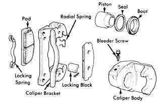 |
| Fig. 5 Front Brake Caliper Assembly for 124 and 131 Models |
Dissasembly, Front - With caliper assembly on bench, remove dust boot. Apply light air pressure toNOTE - Be sure bore not scratched during removal process.
brake fluid inlet union and gently force piston from caliper. Remove piston seal from groove in piston cylinder bore.
Inspection - Clean all components in suitable solven (Fiat LDC). Inspect each part for damage or excessive wear. Replace all piston seals and dust boots.
Reassembly - Fit piston seal in caliper. Insert piston to bottom end of cylinder bore. Piston dust boot on caliper body. Fit caliper body into caliper bracket and reinstall on vehicle.
 |
| Fig. 6 Front Brake Caliper Assembly for 124 Models |
Disassembly, Rear - With caliper assembly on bench, remove dust boot. With a screwdriver, separate piston from plunger. Remove piston seal from groove in piston cylinder bore. Remove cam lever, pivot
pin, and lever. Lift out self-adjusting plunger, plunger seal, disc spring, and spring thrust washer.
Inspection - Clean all components in suitable solvent (Fiat LDC). Inspect each part for damage or excessive wear. Replace all piston seals and dust boots.
Reassembly - Fit self-adjusting plunger complete with seal , disc springs, and thrust washer. Fit parking brake cam lever complete with pivot pin. Fit pivot pin bushing and snap ring. Fit piston sealing ring into caliper cylinder. Screw piston into cylinder until fully seated. Align piston slot so it is opposite bleed connection. Refit dust boot.
REAR WHEEL CYLINDER
 |
| Fig. 7 Exploded View of Rear Brake Caliper for 124 Models |
Disassembly - Remove boots, then remove pistons, seal rings, backing washers and reaction spring. Take out bleeder valve.
Inspection - Clean and dry all parts and inspect for excessive wear or damage. Light damage may be removed by honing; make sure bore size is not altered. Replace all rubber components at each overhaul.
Reassembly - To reassemble, reverse disassembly procedure and note the following: Lightly coat all parts with brake fluid. when assembling to prevent damage. Once assembled, move pistons to ensure they slide freely in cylinder bore.
MASTER CYLINDER
 |
| Fig. 8 Disassembled View of X1/9 Master Cylinder |
Disassembly - Separate fluid inlet union from master cylinder. Disengage boot from cylinder body.
 |
| Fig. 9 Fiat Rear Wheel Cylinder Assembly |
Inspection - Clean and thoroughly dry all parts, then inspect for wear or damage. Light scoring may be remove by honing, make sure honing does not alter size of cylinder diameter. Replace all rubber pieces each time overhaul is performed.
Reassembly - To reassemble, reverse disassembly procedure and lightly coat all components with brake fluid before reassembly.
 |
| Fig. 10 Sectional View of Master Cylinder Assembly for 128 Models |
