For:
- Toyota (1963-75)
- Honda (1963-75)=
DESCRIPTION
Toyota uses two types of regulators, a single element type and a two element type. Two element types consists of a voltage regulator and voltage relay. Single element type has a voltage regulator only.
APPLICATION
Engine Part No.
KC (1969-70)............................................. 22010
3K-C (1970-73).......................................... 22010
2T-C (1971-73).......................................... 22010
BR-C (1969-71).......................................... 33010
18R-C (1972-73)......................................... 33010
3R-B (1965-67)
1900 Sedan.............................................. 31011
Crown
Prior to Eng. 3R 479894........................ 40020
After Eng. 3R 479894............................ 40021
Corona
Prior to Eng. 3R 479894........................ 31010
After Eng. 3R 479894............................ 31011
3R-C (1968-70)
Prior to 10/68.......................................... 31011
After 10/68.............................................. 31010
M (1965-68)............................................... 40021
2M (1965-68)
Prior to 11-68.......................................... 41010
After 11/68.............................................. 41011
4M
1971-72................................................... 41012
1973........................................................ 33010
F (1965-73)
FJ 40 (1965-72)....................................... 40010
FJ 55 (1970-72)....................................... 33010
All 1973 Models....................................... 40011
Honda........................................................ 026002420
1975 Models
Toyota
F & 2F Engines
FJ40.................................................... 60080
FJ55.................................................... 36010
20R Engines
Hilux...................................................... 38050
All Others............................................... 38010
2TC Engine................................................ 38010
4M Engine
To Dec. 1974.......................................... 36010
From Dec. 1974...................................... 38010
Honda
Civic...................................................... 31400-634-671
"All part models start with 27700 prefix"
" Eng. numbers F224280 thru F279664 use part number 27700 40011
 |
| SINGLE ELEMENT TYPE TEST CIRCUIT |
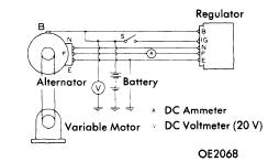 |
| TWO ELEMENT TYPE TEST CIRCUIT |
TESTING
VOLTAGE REGULATOR
Connect test meters to voltage regulator circuit as shown in illustrations. Vary alternator RPM and check voltmeter reading. Increase alternator RPM and check voltage when ammeter register 1/2 of maximum rated alternator output. Voltage should be 13.8 - 14.8 volts. Adjust alternator speed to 3,000 RPM, voltage output should again be 13.8 - 14.8 volts. If voltage is not within specified range, adjust voltage regulator by bending arm to obtain correct setting.
VOLTAGE RELAY
Charge Warning Lamp Type - Connect test, meters as shown in illustration. Increase alternator RPM gradually and note voltage when charge warning lamp goes out. Cut-n voltage should be 4.5 - 5.8 volts. If voltage is not as specified bend voltage relay adjusting arm to obtain correct setting.
Ammeter Type - Connect test meters as shown in illustration. Increase alternator RPM gradually and note voltage. Voltage should be 4.5 - 5.8 volts, if necessary, adjust voltage by bending adjusting arm.
ADJUSTMENT
NOTE - Adjustments are not applicable to sealed units. If points are slighly oxidized or pitted, dress contacts with suitable emery cloth (about 400 grit). If points are oxidized or pitted excessively, replace regulator assembly.
VOLTAGE RELAY
Contact Spring Deflection - Pres on armature and use a feeler gauge to check clearance between armature and point spring. Clearance should be .008 - .018" (.20 - 45 mm). Adjust by bending point holder "A" on relay unit.
 |
| RELAY - WARNING LAMP TYPE TEST CIRCUIT |
 |
| RELAY - AMMETER TYPE TEST CIRCUIT |
VOLTAGE REGULATOR
Armature Gap - Check with a feeler gauge, specified clearance is .024 - .032" (.6 - .8 mm), adjust by bending point holder "A".
 |
| TERMINAL POSITION FOR TWO ELEMENT TYPE REGULATOR WIRING CONNECTOR |
Point Gap - Specified point gap is .010 - .018" (.25-.45 mm). Adjust gap by bending spring holder "B".
Contact Spring Deflection - With armature depressed, check spring deflection with a feeler gauge. Specified deflection should be .008-.024" (.2-.6 mm). If deflection is not as specified, replace regulator assembly.
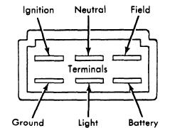 |
| TERMINAL POSITION FOR TWO ELEMENT REGULATOR WITH WARNING LAMP CIRCUIT |
Angle Gap - With armature depressed, check gap with a feeler gauge (see illustration). Specified gap is .008" (.20 mm).
 |
| VOLTAGE RELAY |
 |
| VOLTAGE REGULATOR |