DESCRIPTION
The axle assembly is hypoid gear type with a separate carrier housing. It comes in slightly different models for use in all Toyota vehicles. Two-pinion differential cases are one-piece design while four-pinion cases are two-piece design. The differential side bearing preload is set with adjusting nuts on all models. The pinion bearing preload can be set with a solid spacer and adjusting shim or with a collapsible spacer.
AXLE RATIO & IDENTIFICATION
Toyota uses only one basic type of axle assembly. Any differences in Removal & Installation or Overhaul procedures will be noted where they occur. To determine axle ratio, divide number of ring gear teeth by number of pinion gear teeth.
 |
| Fig. 1 Exploded View of Toyota Two Pinion Differential Assembly (Four Pinion Differential Assembly Shown in Inset) |
 |
| Fig. 2 Rear Axle Assembly for All Models Except Pickup |
REMOVAL & INSTALLATION
AXLE SHAFT & BEARINGS
Axle Shaft Removal, Exc. Pickup - Working through hole in axle flange, remove bolts holding bearing retainer to axle housing flange. Using slide hammer, remove shaft from housing using care not to damage axle seal. If both axles are to be removed, be sure to index mark for reinstallation in original position. If axle housing seal is being replaced, coat sealing lip with grease before installing.
Axle Shaft Removal, Pickup - Raise and support vehicle. Remove brake drum after first removing the mounting bolts. Disassemble brake components and plug open end of brake lines. Disconnect the parking brake linkage and place it out-of-way. Remove nuts retaining brake backing plate to axle housing, then carefully remove axle shaft from vehicle ensuring not to damage oil seal in housing.
 |
| Fig. 3 Rear Axle Assembly for Toyota Pickup |
Bearing Removal & Installation, Exc. Pickup - To remove bearing, grind part way through bearing retainer ring using caution net to nick axle shaft. Cut remaining portion of retaining ring using a cold chisel. Remove split retaining ring and press bearing off shaft. Remove spacer from shaft. To install, place spacer and bearing onto shaft and press into place. Heat new retaining ring to about 300°F (150°C) and press into place. NOTE - The retaining ring will show a faint yellow color when heated to proper temperature. Measure thickness of brake backing plate. Choose proper thickness selective fit gasket, according to thickness of backing plate, then install between backing plate and axle housing flange. NOTE - Carina, Celica, and Corona do not use selective fit gaskets. Place other gasket into position so when shaft is installed it will be between bearing retainer and backing plate. Install axle shaft, check alignment of gaskets, then tighten bolts. Except for selective fit gaskets there is no bearing adjustment.
Bearing Removal & Installation, Pickup - Remove snap ring securing bearing retainer. Install suitable puller onto rear axle bearing case and press axle shaft out of case. Remove bearing from case and press axle shaft out of case. Remove backing plate, drive seated bolts out and separate assemblies. To reassemble proceed as follows: Drive axle shaft oil seal into housing. Fit backing plate on bearing case with index marks aligned. Press serrated bolts into position and install oil seal into bearing case. Fit axle shaft bearing into case. Slide on retainer and fit snap ring. Position new "O" ring on axle housing, then refit axle shaft assembly with backing plate and tighten nuts. Install remaining components in reverse order of removal.
 |
| Fig. 4 Removing Drive Pinion Gear Front Bearing |
PINION SEAL REPLACEMENT
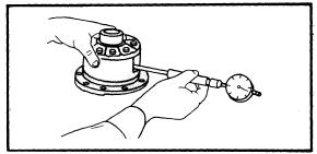
Corona - 1) Disconnect and remove propeller shaft, then set parking brake. Measure and record total pinion preload with pull scale attached to pinion flange at one of the propeller shaft bolt holes. Measurement is made within the small movement caused by the ring gear and axle shaft backlash. Axle shafts are locked by parking brake.
2) Remove pinion shaft nut calking, then remove nut. Using suitable flange puller tool (09557-22010), remove pinion flange. Remove oil seal using suitable puller, then take out oil slinger. Install bearing puller and remove bearing, then withdraw spacer and measure. If spacer is larger than minimum specification, it may be reused by adding an additional shim. If spacer is shorter, use new spacer. Assemble spacer and shim (if used) onto pinion shaft.
Minimum Spacer Length
Application Specification
Corona In. (mm)
6.7" Ring Gear................................................. 2.13 (54.0)
7.1" Ring Gear................................................. 2.40 (61.0)
 |
| Fig. 5 Installing Oil Seal |
3) Install bearing and oil slinger. Apply grease to seal lip and install in carrier. NOTE - Fit oil seal to a depth of .06" (1.5 mm) on Mark II Sedan, or .15" (4.00 mm) on Mark II Station Wagon. Using tool attached to pinion flange, install pinion flange. Remove tool, install new nut and tighten. Rotate pinion in both directions to seat bearing, then measure preload in same manner as before. Preload must be equal to original value plus 1.5-2.0 lbs (.7-.9 kg). If preload is insufficient, tighten nut in 7.2 ft. lbs. (.97 mkg) increments until it is to specification. If 145 ft. lbs. (20.0 mkg) is reached without preload being within specification, loosen nut and begin retightening again.
NOTE - On all other modes, carrier removal is suggested before replacing pinion seal.
DIFFERENTIAL CARRIER REMOVAL & INSTALLATION
 |
| Fig. 6 Removing Differential Carrier |
Drain oil from axle housing. Loosen hub nuts, and remove wheels. Disconnect and place propeller shaft out of the way. Remove axle shafts as previously described. NOTE - Take care not to damage oil seal if it not scheduled for replacement. Loosen bolts and remove differential carrier. To install, reverse removal procedure, noting the following: Coat both sides of carrier-to-housing gasket with sealer before installation. Fill axle housing with 90W gear oil.
OVERHAUL
DISASSEMBLY
1) Mount carrier on suitable work stand. Punch aligning marks on bearing cap and carrier to prevent intermixing of left and right caps. Remove adjusting nut lock bolt. Remove side bearing bolts, caps, and adjusting nuts. Take out differential case assembly with bearing cups. Note number and thickness of any shims. Remove pinion flange bolt using suitable tool to hold the flange. On some models, drive pinion will fall out if not restrained.
 |
| Fig. 7 Removing Drive Pinion and Flange on Pickup |
2) Using suitable puller (09557-22010), remove flange from pinion shaft. On pickup models, puller is not required. Using suitable puller, remove oil seal. On pickup models, seal can be pried out in lieu of special tool. Withdraw oil slinger.
3) With suitable puller, remove front pinion bearing, then press drive pinion out of rear of carrier. On pickup models, drive pinion removal does not require a press. Press out front and rear bearing cups. With drive pinion shaft installed in suitable press, remove rear bearing. Use caution to avoid deforming shim that adjusts pinion depth (height). Remove side bearings from differential case. NOTE - Cutaways are provided in case for clearance of puller hooks. Straighten out lock plates on ring gear bolts, index mark ring gear and case, then remove bolts.
 |
| Fig. 8 Removing Rear Bearing from Drive Pinion Gear |
4) Mount differential case and ring gear assembly in vise so ring gear teeth are pointed down. Tap ring gear from case using a brass hammer. Measure backlash between differential pinion and side gear for reference during reassembly. Backlash should be .002-.008: (.05-.20 mm). On two-pinion differentials, remove pinion gear shaft retaining pin from case. Drive out pinion gear shaft, remove pinion gears, side gears and thrust washers. On four-pinion differentials, separate case cover and remove pinion shaft holder, side gears and thrust washer.
REASSEMBLY & ADJUSTMENT
 |
| Fig. 9 Installing Side Bearings on Differential Case |
Case Assembly - 1) Lubricate all components with hypoid gear lubricant. On two-pinion models, assemble side gears and pinion gears into differential case. Make sure oil groove, if present, on side gear thrust washer faces toward gear. On four-pinion types, install side gears, thrust washers, differential pinions, pinion shaft holder, differential shaft, and pinion shaft. Install differential case cover and tighten bolts. Note that long bolts serve to lock differential tight.
2) Check backlash between side gears and pinion gears. If backlash is not .002-.008" (.05-.20 mm) install suitable selective fit thrust washers. Install pinion shaft lock pin, if equipped, and peen over hole.
 |
| Fig. 10 Measuring Ring Gear Runout |
3) Press differential side bearings onto differential case. Heat ring gear in oil or water bath to approximately 212°F (100°C), then quickly wipe off gear and install on differential case. Fit bolts and tighten evenly, then bend over lock tabs. Install differential case assembly on differential carrier and measure ring gear runout.
4) If runout is within specifications, remove differential carrier and bend up on ring gear lock plate. If runout exceeds specifications, remount ring gear 180° from original position on differential case. If this fails to bring ring gear into specifications, remove ring gear from case and examine runout. If case runout is within range specified for ring gear, then ring gear is at fault and should be replaced. Remove ring gear and case assembly from carrier.
 |
| Fig. 11 Toyota Master Gauge for Measuring Drive Pinion Installed Height |
Drive Pinion Depth - Install drive pinion cups into carrier. Adjust pinion depth using Toyota Master Gauge or equivalent. Insert drive pinion rear bearing onto suitable base rod, then install base rod head. Insert this assembly into carrier from the rear. Install front pinion bearing into carrier from front end. Install collar, preload flange pulley and nut onto front end of base rod. Using a spring scale and thin cord, measure preload of drive pinion bearings. tighten nut until preload is within specifications (see specifications). Install master gauge into differential side bearing bores, then install bearing caps and tighten. Select a shim that will just fit between master gauge and base rod head. One shim or none must be used: do not use more. After selecting the shim, remove all components of master gauge kit from carrier. Install shim onto drive pinion, if it has a chamfered edge, install that edge toward pinion gear; press rear bearing into place.
NON-COLLAPSIBLE (SOLID) SPACER
Pinion Bearing Preload - 1) Install bearing spacer onto pinion shaft and insert assembly into carrier from rear. Insert shims (if any) that were removed during disassembly onto pinion shaft.
2) Install front bearing, oil deflector, flange, washer and nut. Torque pinion flange nut to specifications. Install preload flange onto pinion flange.
3) Using torque wrench, measure pinion bearing preload. If not to specifications, shims in front of preload spacer must be changed. If preload is too great, increase shim thickness: if preload is too small, decrease shim thickness.
4) Use either two shims or non for adjustment. If thicker shim pack is needed, use thicker shims, not more shims. When preload is correct, remove flange, install oil seal and reassemble
COLLAPSIBLE SPACER
 |
| Fig. 12 Installing Pinion Flange |
Pinion Bearing Preload - 1) Measure used spacer, if less than specifications, discard and use new spacer. If old spacer is longer than minimum specifications, it may be reused with a shim .012" (.03 mm) thick.
2) Fit spacer on drive pinion shaft and insert assembly into carrier from rear. If shim is to be used, install it on shaft. Insert bearing into front end of carrier. Insert oil slinger and install oil seal. On Mk II only, ensure oil seal is installed .060" (1.5 mm) from front edge of carrier bore.
 |
| Fig. 13 Measuring Side Bearing Preload |
3) Apply grease to oil seal lip before installation. Using suitable pinion flange installing tool (09557-22010), fit pinion flange. Turn nut on special tool to seat pinion flange, then remove tool. Install washer and new nut and tighten to approximately 80 ft. lbs. (11.0 mkg).
4) Install preload flange and measure preload with torque wrench. If preload is less than specifications, tighten pinion flange nut more and recheck. If preload exceeds maximum specifications, disassemble and add shims (or replace collapsable spacer). Reassemble and recheck
Minimum Spacer Length
 |
| Fig. 14 Measuring Ring Gear Backlash |
Application Specification In. (mm)
Corona
6.7" Ring Gear....................................... 2.13 (54.0)
7.1" Ring Gear....................................... 2.40 (61.0)
Backlash & Side Bearing Play - 1) Assemble bearings in cups and install onto carrier. Install differential assembly into carrier, then fit adjusting nuts. Put bearing caps on in original position. Tighten bolts carefully, while checking that adjusting plunger touches flange side of ring gear. Tighten flange side adjusting nut until a slight backlash remains. During operation, rotate ring gear through several revolutions to seat side bearings. Tighten tooth side nut just to the point where there is no differential end play when measured with dial indicator. At this point tighten tooth side nut just tot the point where there is no differential end play when measured with dial indicator. At this point tighten tooth side nut on additional 1-1½ notches to preload side bearings.
2) Confirm that some backlash is still present. Install preload flange onto the pinion shaft flange and measure preload. If within specifications go on to next step; if not tighten tooth side adjusting nut on more notch and recheck.
3) Install dial gauge so that plunger is perpendicular to ring gear tooth. Measure ring gear backlash. If not within specifications, turn left and right adjusting nuts to shift differential assembly in proper direction. If left side is loosened one notch, the right side must be tightened one notch to maintain side bearing preload. Continue procedure until backlash is within specifications. One notch will change backlash .002" (.06 mm). Tighten side bearing cap bolts. Check gear tooth contact pattern. See Gear Tooth Contact Pattern at beginning of this section. Install differential carrier.
 |
| Fig. 15 Exploded View of Limited Slip Differential |
LIMITED SLIP DIFFERENTIAL
Disassembly - Remove case cover and take out side gear side thrust washer, lock pin, left and right cluch and differential pinion
Inspection - Visually inspect all components for excessive wear or damage, then replace those parts found defective.
Reassembly and Adjustment - 1) Fit ring gear to differential case and check runout. Dial gauge reading should be .004" (.10 mm); correct, if necessary, as previously indicated.
2) Adjust clearance between differential case, side gear and clutch using thrust washers that will provide a clearance of .001-.004" (.03-.11 mm). Proceed as follows to select proper thrust washer:
 |
| Fig. 16 Measuring Mounting Distance |
3) Install case cover and tighten bolts. Check differential case mounting distance as shown in illustration, then record value. With side gear and clutches mounted in suitable vise measure distance between outside edges of side gears; use a micrometer. The difference between the two recorded figures indicates necessary thrust washer thickness. To complete reassembly, reverse removal procedure

