Showing posts with label Alfa Romeo. Show all posts

Saturday, January 3, 2015

Bosch Alternators 1974

Car Manufacturers Covered:

  • Alfa Romeo
  • Audi
  • BMW
  • Capri
  • Fiat 128 & X1/9
  • Mercedes-Benz
  • Opel
  • Porsche
  • Saab
  • Volkswagen
  • Volvo 4 Cylinder
CHANGES, CAUTIONS, CORRECTIONS
BATTERY INSTALLATION, BATTERY CHARGING, OR USING A BOOSTER BATTERY TO START ENGINE - Reversed polarity or excessive voltage will result in damage to alternator system. Note the following to prevent damage:
Battery Installation - Negative battery terminal must be connected to ground. Positive terminal must be connected to starter lead. DO NOT reverse battery leads.
Battery Charging - If a Quick Charger is used, both battery cables must be disconnected from the battery. DO NOT use a Quick Charger to provide starting voltage.
Booster Battery (For Engine Start) - Booster battery must be connected with negative lead to negative terminal of battery and positive lead to positive terminal of battery. DO NOT reverse battery leads.
                                   APPLICATIONS
Model                             Type No.                          Part No.
Alfa Romeo ................ K1 14V 45A 22 ............. * 0 120 400 848
Audi .................................. ... ............................. ** 059 903 017D
BMW
     2002, 2002A .......... K1 14V 45A 22 ............. * 0 120 400 752
     2002 tii ................... K1 14V 45A 22 ............. * 0 120 400 794
     3.0 .......................... K1 14V 45A 20 ............. * 0 120 400 702
Capri
     4 Cyl. W/A.C ............... ... .............................. *** D4RY-C
     4 Cyl. All Others ......... ... .............................. *** D4RY-B
     V6 W/ A.C. .................. ... .............................. *** D4RY - D
     V6 All Others .............. ... .............................. ***D4RY-A
Fiat 128 & X1/9 ................ ... ............................. * 0120 300 568
Mercedes Benz
     230, 240D .................... ... .............................. **** 0041 546 902
     280 ........................ K1 14V 55A 20 .............. **** 0041 541 802
     450 ........................ K1 14V 55A 20 .............. **** 0031 545 602
Opel ................................ ... ................................ * 0 120 400 620
Porsche
     4 Cyl .......................... ... ................................ ***** 022 903 023
     6 Cyl .......................... ... ................................ *****911 603 118 00
Saab
     99 .............................. ... ................................. *0120 400 850
     V4 ............................. ... .................................  *0120 400 657
Volkswagen 
     Type 1 ........................ ... ................................ * 0120 400 836 or 862
     Type 2 & 4 ................. ... ................................ * 0120 400 721
     Dasher ........................ ... ................................ * 0120 489 532 or 535
Volvo 
     140 ............................. ... ................................ * 0120 400 756
     164 ............................. ... ................................ * 0190 601 011
* - Bosch Part No.
** - Audi Part No.
*** - Motorcraft Part No.
**** - Mercedes Benz Part No. 
***** - VW Part No.
DESCRIPTION
Bosche alternators are conventional three-phase, self-rectifying type alternators. Nine rectifier diodes are connected to the stator windings (three to each phase lead). The diodes change the alternator A.C. voltages to D.C. voltages coming out of the "B+" and "D+" terminals of the alternator.
                                  SPECIFICATIONS
Alternator*                     Amp Output @ RPM                     Max Current
G1 14V 33A 27 ...................  33 @ 5000 ................................... 40A
K1 14V 35A 20 ................... 23 @ 2000 .................................... 35A
K1 14V 45A 20 .................... 30 @ 2000 ................................... 45A
K1 14V 45A 20 .................... 30 @ 2200 ................................... 45A
K1 14V 50A 20 .................... 33 @ 2000 ................................... 50A
K1 14V 55A 20 .................... 36 @ 2000 ................................... 55A
K1 14V 55A 22 .................... 36 @ 2200 ................................... 55A
* - Charging voltage: 14.
Field Coil Resistance - 4.0 ohms + 10% measured at slip rings at normal ambient temperature.
Stator Windings Resistance - .2 ohms + 10% measured between the phase output terminals
ON VEHICLE TESTING
NOTE - Off vehicle testing is explained as part of Overhaul procedure in this article.
WIRING CONTINUITY TEST
Disconnect terminal plug from rear of alternator and connect a voltmeter negative terminal to ground. With Ignition "ON", connect positive lead to each of  the connector wires, in turn. Voltmeter should read battery voltage as each positive connection is made. If proper voltage is not read, trace each wire to find fault.
VOLTAGE DROP TEST - GROUND SIDE
Connect voltmeter between negative terminal of battery and alternator housing. Start engine and run at approximately 3000 RPM. If voltmeter reading exceeds .25 Volts, a high resistance in negatvie side of charging circuit is indicated. If so, check for loose, dirty, or corroded connections.
OUTPUT TEST
Disconnect terminal plug from rear of alternator and connect ammeter, in series between alternator center terminal and corresponding socket in terminal plug. Also connect a jumper lead between the "D+" terminal and its corresponding socket in terminal plug. Start engine and run at approximately 3000 RPM. Turn on headlights and leave on for five minutes. Ammeter should read maximum alternator amperage at normal operating temeperature.
REGULATOR CONTROL VOLTAGE TEST
Connect a voltmeter between main terminals of battery. Connect an ammeter, in series, between "B+" terminal of alternator and corresponding terminal of connector plug. Connect a jumper lead between alternator "D+" terminal and corresponding terminal of connector plug. Start engine and increase speed to approximately 3000 RPM. Run engine until charging rate falls below 10 amps. The voltmeter should then read 14.1 - 14.4 Volts. If these readings are not obtained, replace regulator.
NOTE - The test cables should not be removed or the load excessively reduced during the diodes. The control lamp should not go on at any time during the test.
BOSCH ALTERNATOR (TYPICAL)

OVERHAUL
DISASSEMBLY
NOTE - On 0 120 400 600 series alternators, lift carbon brushes with hook and secure them, prior to disassembly (see illustrations).
1) Remove nut, pulley, hub and key. Mark location of alternator in blower housing. Unscrew brush
LIFTING CARBON BRUSHES
(0 120 400 600 Series)
plate assembly and remove from alternator. Remove bolts from end frame, then remove frame and field rotor. Press rotor out of end frame. Press ball bearing off rotor. Remove insulating conduit from wires and cut wires as close to soldered joints as possible.
2) The diodes may be tested at this point, prior to further disassembly. Care should be exercised with insulating busings under positive diode carrier. To remove negative carrier, extract threaded studs. When one rectifying diode has been damaged due to short circuiting, the three complementing diodes must be replaced also. Unscrew nuts on both "B+" terminal bolts and lift positive diode carrier (heat sink) up and back.
TESTING & REPAIRING
Diode Assemblies - test diodes with a suitable alternator tester (EFAW 192) before dismantling slip ring end frame further. CAUTION - Do not lay positive diode carrier on housing or false reading will be obtained. Disconnect conductor from "D+" to the exciter diodes at the exciter diodes heat sink. Unscrew spring and brush holder and remove from alternator. Unsolder stator lead and negativediode connection. Unscrew exciter diodes heat sink  and remove together with positive diodes heat sink.
NOTE - Before further testing, lightly clean all components in gasoline or trichlorethylene, but do not soak.
Stator - Test stator for short circuits to ground, using suitable tester (EFAW 84). Test voltage should be 40V AC. Measure resistance of stator windings between phase connections. See specifications for proper value.
Rotor  - 1) Test claw pole rotor for short circuits to ground. Test voltage should be 40V AC. Measure resistance of exciter (field coil) in rotor with ohmmeter. See Specifications for proper value. Turn down slip rings on a lathe, using suitable tailstock chuck (EFAW 75 or GDF 85 R 3).
2) After turning, check concentricity of slip rings with dual gauge. Runout should not exceed .001" (.03 mm). Minimum diameter of slip rings may be 1.25" (31.5 mm). Maximum runout of pole wheel must not exceed .002" (.05 mm).
Diode Replacement - 1) On all except 0 120 400 600 series alternators, set diode plate on press die and force diodes out with plunger. Place diode plate (without diodes) onto suitable guide pilot (EFLJ 57/0/5) and set diode seat with suitable sleeve (EFLJ 57/0/3). Smear silicone oil on diode seat, place diode palte on press die and press diodes into position. After pressing in, test all diodes.
2)  On 0 120 400 600 series alternators, set slip ring end frame on press die and force out defective diode. Coat diode seat with silicone oil and press in new diode. Test all diodes after replacement.
Drive End Frame - Check ball bearings for wear and replace as necessary. Lubricate bearings on one side. Press ball bearing into drive end frame with shielded side downward. Screw on retainer plate. Press ball bearing onto rotor (slip ring end), then press drive end frame onto rotor.
Carbon Brushes - Unsolder and replace carbon brushes. Do not allow solder to run into copper stands of brush leads. Minimum brush length is .55" (14 mm). After installation of new brushes, test for free movement.
REASSEMBLY & TESTING
1) On all except 0 120 400 600 series alternators (steps 1 through 4), fit negative diodes heat sink and clamps. Screw in double end bolts (shorter threads outward). NOTE - Left clamp is longer than right. Replace insulating washers and bushings. Test terminal bolt "B+" for short circuit to ground. Test voltage should be 80V AC.
2) Position positive diodes heat sink (carrier) and secure with insulating and spring washers. NOTE -
INSTALLATION OF DIODES
Use insulating cap NO. 1 120 502 000 instead of insulating washer on bolt nest to terminal marked "D+/61".
Tighten hex nuts.
3) Place stator in slip ring end frame. Draw positive and negative diode leads together and lip through an insulating sleeve. Push sleeve over lead of exciter diode and stator connections cable. Crimp a metal ring around end of leads and solder. Cut off any excess wire protruding through ring. Reposition wiring and attach in holding clamps.
4) Side insulating sleeve over exciter diode terminal. Insulating sleeves of stator connection lead must  project over edge of negative diodes heat sink. Clamp connections firmly. 
5) On 0 120 400 600 series alternators (step 5 through 7), test both "B+" terminal bolts for short circuit to ground. Test voltage should be 80V AC. Before fitting exciter diodes heat sink (carrier), solder three positive diode terminal leads onto heat sink from below.
6) After fitting exciter diodes heat sink, solder stator leads, negative and exciter diodes to the "COMB". NOTE - Use caution, do not overheat negative diodes. Install brush holder. Raise and secure carbon brushes before installing. Screw conductor "D+" onto exciter diodes heat sink.
7) Place wave spring washer into ball bearing fit. Rub ball bearing seat with suitable lubricant. Insert rotor with drive end bearing into slip ring end frame and secure. Springs are to be set onto carbon brushes by pressing on brush with a screwdriver. Brush spring pressure will seat brushes automatically.
8) Rub suitable lubricant into ball bearing seat of slip ring end frame. Install claw pole rotor with drive end frame. Check position of stator relative to end frame. Position brush holder plate. Tighten screws. Install fan belt pulley. Coat newly installed positive diodes with chlorinated rubber lacquer.

Sunday, January 29, 2012

Alfa Romeo 1975 Wheel Alignment Repair Guide

ALFA ROMEO SPECIFICATIONS AND ADJUSTMENTS

TIRE INFLATION (COLD)
Before attempting to check or adjust wheel alignment, check that tire pressures are to specifications give on driver's door lock pillar

RIDING HEIGHT
Before attempting to check or adjust riding height, vehicle must be in static loaded condition. To load vehicle, fuel tank must be full, and weights placed in vehicle to simulate full passenger load (620 lbs. on 4 Dr. and 310 lbs. on 2 Dr.). Disconnect front and rear shock absorber. Disconnect stabilizer rods of front and rear suspension. Bounce vehicle several times and allow suspension to take up a static position.


All Models (Front) - Measure distance from lower control arm bushing to floor and front bottom of steering knuckle to floor. The difference between these two measurements should coincide with specifications. If adjustment is necessary, remove spring on affected side. See Alfa Romeo in SUSPENSION Section. Using suitable spacer between spring and its seat, adjust height to specifications. After reinstalling spring, check front suspension height.

All Models (Rear) - Measure distance between rear axle housing and rubber bumper pad. If measurement is not within specifications, remove spring on affected side. See Alfa Romeo in Suspension Section. Using suitable spacer bewtween spring and its seat, adjust height to specifications. After reinstalling spring, recheck clearance.

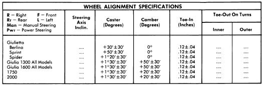
CASTER
Caster angle should be checked under static load with shock absorbers disconnected at one end. Difference in caste angle between left and right front wheels, should not exceed 0°20'. If caster angle is not within specifications, loosen lock nuts on upper control arm strut rods and lengthen or shorten strut rods to obtain specified angle. Retighten lock nuts.

CAMBER
Camber angle difference between left and right front wheels should not exceed 2/3°. Adjust camber angle to specifications by adding or removing shims between lower control arm and frame.

TOE-IN
Place wheels in straight-ahead position and measure toe-in. If toe-in is not to specifications, adjust by loosening lock nuts and adjusting tie-rods. Tighten lock nuts and recheck toe-in.

Alfa Romeo 1974 Wheel Alignment Repair Guide

ALFA ROMEO SPECIFICATIONS AND ADJUSTMENTS

TIRE INFLATION (COLD)
Before attempting to check or adjust wheel alignment, check that tire pressure are to specifications given on driver's door lock pillar

RIDING HEIGHT
Before attempting to check or adjust riding height, vehicle must be in static loaded condition. To load vehicle, fuel tank must be full, and weights placed in vehicle to simulate full passenger load (620 lbs. on 4 Dr. and 310 lbs. on 2 Dr.) Disconnect front and rear shock absorber. Disconnect stabilizer rods of front and rear suspension. Bounce vehicle several times and allow suspension to take up to static position

All Models (Front) - Measure distance from lower control arm bushing to floor and from bottom of steering knuckle to floor. The difference between these two measurements should coincide with specifications. If adjustment is necessary, remove spring on affected side. See Alfa Romeo in SUSPENSION Section. Using suitable spacer between spring and its seat, adjust height to specifications. After reinstalling spring, check front suspension height.

All Models Rear - Measure distance between rear axle housing and rubber bumper pad. If measurement is not within specifications, remove spring on affected side. See Alfa Romeo in SUSPENSION Section. Using suitable spacer between spring and its seat, adjust height to specifications. After reinstalling spring, recheck clearance
Steering Link Specifications
Application                 Left & Right                 Center
All Models.........10.4-11"...................20.86-21.65"

CASTER
Caster angle should be checked under static load with shock absorbers disconnected at one end. Difference in caster angle between left and right front wheels, should not exceed 0°20'. If caster angle is not within specifications, loosen lock nuts on upper control arm strut rods and lengthen or shorten strut rods to obtain specified angle. Retighten lock nuts.

CAMBER
Camber angle difference between left and right front wheels should not exceed 0°40'. Camber angle is not adjustable. If not within specifications, check suspension system for damage. Repair or replace necessary components.

TOE-IN
Lock steering wheel in center position so front wheels are in straight-ahead position. Start with steering link on steering box side, and set corresponding wheel to initial toe-in of 06". mEasure length of this steering link. Set steering link on opposite side to .20" less than this measurement. Now adjust center steering link to obtain .06' toe-in on wheel nearest steering box. With toe-in set, measure length of each steering link. If not within specifications, cause may be due to body distortion. Repair as necessary.


Alfa Romeo 1963-73 Wheel Alignment Repair Guide

1963-73 ALFA ROMEO SPECIFICATIONS AND ADJUSTMENTS


TIRE INFLATION (COLD)
Before attempting to check or adjust wheel alignment, ensure that tires are properly inflated. Giuletta requires 20 psi front and 21 psi rear. All other models 24 psi front and 26 psi rear. Check tire pressures given against specifications on driver's door lock pillar to verify pressure.

RIDING HEIGHT
Before attempting to check or adjust riding height, vehicle must be in static loaded condition. To load vehicle, fuel tank must be full, and weights placed in vehicle to simulate full passenger load. Disconnect front and rear shock absorbers. Disconnect stabilizer rods on front and rear suspension. Bounce vehicle several times and allow suspension to take a static position


All Models Front Exc. Giuletta - Measure distance from lower wishbone shaft to floor and from bottom swivel pin to floor. Calculate difference between measurements and if not within specifications, adjustment must be made before preceding with wheel alignment checks. Remove spring on side affected with suitable tool (A.2.0169) and add suitable spacer with chamfered edge down. Install spring and recheck front suspension height.

All MOdels Rear Exc. Giuleta - Measure distance between rear axle housing and rubber pad. If measurement not within specifications, adjustment is necessary before proceding with wheel alignment checks. Remove spring. See Coil Springs in SUSPENSION Section. Insert spacer of suitable thickness between spring and its seat. Install spring and recheck rear measurement.

CASTER
Guiletta - Caster is nonadjustable. If not within specifications, check suspension for damage. Repair or replace components as necessary.

All Others - Caster angle should be checked under static load with shock absorbers disconnected at one end. Difference in caster angle between left nad right front wheels should not exceed 1/3". If caster angle is not within specifications, loosen lock nuts on upper control arm stud rods and lengthen or shorten strut rods to obtain specified angle. Retighten lock nuts.

CAMBER
Giuletta - If camber not within specifications, loosen bolts for brackets on upper wishbones. Add or remove shims between bracket and body until camber set to specifications. Tighten bolts.

All Other Models - Camber is nonadjustable. If not within specifications, check suspension for damage. Repair or replace components as necessary.

TOE-IN
Giuletta - Position wheels in straight ahead position. Loosen track rod lock nuts. Adjust left hand lateral track rod to set left front wheel to zero toe-in. Measure length of left track rod and adjust right track rod to same length. Adjust right track rod by loosening central track rod until right wheel set to zero toe-in. Reduce both lateral track rods by equal amounts to set toe-in to specifications. Tighten all lock nuts.

All Other Models - Position wheels in straight ahead position. Loosen lock nuts on left hand tie rod and rotate tie rod until toe-in on left wheel is 1/16". Measure left tie rod and adjust right tie rod to same length. Adjust right track rod by loosening central track rod lock nuts and rotating central track rod until right wheel set to 1/16" toe-in. Tighten all lock nuts. Measure both tie rod lengths and central track rod. If not within specifications, check suspension for damaged components. Repair or replace as necessary.


Saturday, November 19, 2011

1975 Vehicles Jacking and Hoisting Guide

Click to Enlarge
ALL MANUFACTURERS
NOTE - These illustrations are not intended to represent exact structure of the manufacturer's frame, underbody or body outline. These are presented only to give the mechanic some point of reference.

FRAME AND UNDERBODY
The following illustrations indicate areas (parts) of the underbody and frame which may be used to raise and support the vehicle, using either floor jack or hoist. Thse points are indicated by shaded areas on the frame (see sample illustration).

OUTERBODY
Those points designated on the outline of the body were specifically designed to facilitate the use of the vehicle's own jack, but may also be used to raise and support the vehicle by means of floor jack or hoist. These jacking points are indicated by circular dots on the outline of the body (see sample illustration). If floor jack or hoist is employed, extreme care should be exercised to prevent damaging the outer body shell.

Click to Enlarge Photo


1975 Vehicles Ball Joint Checking

ALFA ROMEO
All Models - Check working surfaces of ball pins and their seats, and ball joint studs for damage or wear. Axial play should not exceed specifications (.04"). Replace complete ball joint unit when indicated

BMW
All Models - With lower control arm removed, measure axial (up and down) movement of ball joint stud. If movement exceeds .0945", replace ball joint.

COLT
All Models - With components removed from control arm and ball joint still installed, check the following: Horizontal and vertical free play (0") and ball joint rotation starting torque 4-7 ft. lbs. (.6-1.0 mkg). Replace ball joints if correct specifications are not obtained

COURIER
All Models - Check working surfaces of ball joints and studs for wear or damage. End play should not exceed .031" (.8mm). If end play is excessive, replace ball joint.

DATSUN
All Models (Exc. 620 Pickup) - Remove lower control arm. Measure axial movement by lifting and depressing ball joint stud. Difference between these two measurements is axial movement. Using suitable spring tension gauge attached to top of ball joint stud measure force (INCH lbs.) required to move ball joint stud laterally. If either measurement is not within specifications, replace ball joint.
Ball Joint Specifications
  Application                      Axial                     Lateral INCH Lbs. (cmkg)
B210..................   .004-.012"(.1-.3 mm)..........................  52 (60)
610,710 and 280Z....    .004" (.1 mm)..............................   35 (40)

FIAT
All Models - With vehicle raised and supported under lower control arms, grasp wheel at top and bottom and try to shake wheel. If any movement is noted, control arm must be removed for further inspection

HONDA
All Models - Raise and support front of vehicle. Attach dial indicator onto lower control arm with indicator tip on steering knuckle near ball joint. Place pry bar between lower control arm and steering knuckle.

JAGUAR
All Models - Upper ball joint must be replaced. If signs of wear or play are evident. The lower ball joint is adjustable with shims if axial play exceeds .004-.006" (.10-.15 mm). Shims must not be removed to take up excessive wear in ball pin and socket. If parts are excessively worn, replacement is required.

LUV
With vehicle raised and supported under lower control arms, grasp wheel at top and bottom. Try to shake wheel and if any movement is noted, inspect front suspension for wear or damage.

MAZDA
All Models - Check ball joint dust seal for wear or damage and, if necessary, replace seal. Ball joint end play must not exceed .039" (1 mm). If end play exceeds specifications, replace ball joint.

OPEL
All Models - Raise and support front of vehicle. Inspect ball joint rubber boots for damage and replace as necessary. Using suitable gauge (J-23745) measure axial play. If axial play is more than .080" (2 mm), ball joint must be replaced.

PEUGEOT
All Models - Inspect ball joints for roughness or excessive wear. Replace ball joints as necessary.

PORSCHE
All Models - When moving ball pin some friction torque should be felt. If ball pin can be moved without resistance and end play is shown, replace ball joint.

RENAULT
All Models - Inspect ball joints for wear or excessive play. Replace ball joint as necessary.

SAAB
All Models - If ball joint exhibits excessive play, it must be replaced as a complete unit.

SUBARU
All Models - Check ball joint for excessive play by pushing and pulling on ball joint stud. Allowance loosness is less than .012". If play exceeds this specification, ball joint must be replaced.


Wednesday, November 16, 2011

Wheel Bearing Adjustment Guide

ALFA ROMEO
All Models - While rotating hub, tighten spindle nut to 18 ft. lbs. Loosen nut, then retighten to 7 ft. lbs. Back off on nut 1/4 turn and install cotter key. If slot in spindle nut does not align with hole in spindle, tighten nut until it is possible to insert cotter key. After cotter key is installed, ensure that bearing retainer plate can be easily rotated by insterting a screwdriver in plate holes

AUDI
NOTE - The following procedure can only be performed using special tools indicated.

Model 100 (Front) - 1) Raise and support front of vehicle. Remove lower wheel bolt and replace with special wheel bolt adapter (V-104) and special dial indicator (G-43). By means of retaining screw on special tool (V1-104), adjust dial indicator to pretensioned position of 1 millimeter.

2) Grasp wheel at front and rear. First push inward on front while pulling outward on rear, record dial indicator reading. Reverse this procedure and record dial indicator reading. Difference between these two readings is wheel bearing play. If play exceeds .04-.07 mm, adjustment will be necessary.

3.) Remove cotter pin and castle nut. If there was too much play, tighten spindle nut until play is within specifications. If there was insufficient play, remove wheel, spindle nut and its shim. Replace and tighten spindle nut. Using 1 millimeter feeler gauge, loosen spindle nut until it is possible to insert feeler gauge between spindle nut and wheel hub. Attach special hub puller (V-26) and withdraw hub until it is firmly in contact with spindle nut. Remove puller and retighten spindle nut until it is within specifications

Model 100 (Rear) - Raise and support rear of vehicle. Remove grease cup and one wheel bolt. Attach special dial indicator (30-43), using wheel bolt adapter (40-104) and attachment (10-22). Dial indicator activator foot should be pretensioned to 1 millimeter against the stub axle. Grasp wheel at front and rear. Move wheel on horizontal axis. If reading on dial indicator is not .02-.04mm, adjustment will be necessary. Adjust by loosening or tightening spindle nut

NOTE - Fox front wheel bearing is not adjustable. Torque stub axle nut to 13 ft. lbs.

Fox (Rear) - Remove grease cup, cotter pin and castle nut. Tighten spindle nut and loosen for adjustment. Adjust by lightly tightening spindle nut until plain washer (beneath spindle nut) can just be moved from side to side, using screwdriver. Thin adjustment will correspond to .0012-.0027" (.03-06 mm) wheel bearing play.

AUSTIN
Austin Marina - Raise and support vehicle so that front wheel is not touching ground. Remove grease cup and attach suitable magnetic base dial indicator with base on brake drum and actuating foot touching spindle. Bearing wobble should be from .001-.005". If adjustment is required remove cotter pin and slacken castle nut. Torque castle nut to 5ft lb. while spinning wheel. Stop wheel, slacken castle nut, and retighten castle nut, finger tight only. Reinstall cotter pin. NOTE - At minimum end-float figure given a considerable amount of movement will  be felt in the front wheel. Do not reduce end-float below .001".

BMW
2002 Models - While rotating wheel hub, tighten castle nut to 22-24 ft. lbs., then rotate hub at least two more times. Loosen castle nut until bearing end play is noticed. Tighten castle nut to maximum of 2.2 ft. lbs., then loosen nut to nearest hole an install cotter key. NOTE - After adjustment, slotted washer should move easily, without noticeable resistance.

3.0 Si and 530 i Models - While rotating wheel hub, tighten castle nut to 7 ft. lbs. Loosen castle nut approximately 1/4 turn. Insert screwdriver in recess of bearing retainer washer and ensure washer can be rotated easily. Install suitable gauge holder (BMW 00 2 500) on wheel hub and install dial indicator with tip touching front axle stub. Move wheel hub back and forth several times and check bearing end play. Adjust castle nut until bearing end play is .0008-.0024". NOTE - Set bearing end play as close to lowest limit as possible. Install cotter key.

CAPRI
All Models - Rotate wheel, hub and drum assembly while turning adjusting nut to 17-25 ft. lbs. Back off nut one-half turn. Retighten adjusting nut to 10-15 INCH lbs. Reinstall cotter pin and check front wheel rotation

COLT
All Models - Tighten adjusting nut to 14.5 ft. lbs. After seating bearing components, loosen nut to 0 ft. lbs. Now make final adjustment to 3.6 ft. lbs. After installing lock cap, insert cotter pin. NOTE - Do not loosen adjusting nut more than 15 degrees to align spindle holes.

COURIER
All models - While rotating wheel, hub and drum assembly, tighten adjusting nut to 17-25 ft. lbs. Back adjusting nut off 1/2 turn and retighten nut to 6-8 ft. lbs. Install new cotter key and check wheel rotation.

DATSUN
All models - Tighten spindle nut to torque specifications in following table. Spin wheel and retorque spindle nut. Loosen nut according to specifications in following table and then tighten to align cotter key hole. Insert cotter pin.

Wheel Bearing Adjustment
Application                        Torque                  Loosen
B210..................................22-25....................90 Degrees
Pickup................................22-25....................40 to 70 Degrees
All Other.............................18-22...................60 Degrees

Model 124 and 131 - While rotating hub, torque spindle nut to 14.5 ft. lbs. Completely loosen nut and retighten to 5 ft. lbs. Loosen nut 30 Degrees and stake collar of spindle nut into machined slot on spindle. Attach dial indicator with magnetic base on brake drum and actuating foot on spindle. Hub end play should not exceed .004". NOTE - When ever spindle nut has been removed it must be replaced with a new nut.

FIAT (Cont.)
Models 128 and X 1/9 - Tighten front and rear spindle nuts to 112 ft. lbs. When spindle nuts are properly tightened, stake collar of spindle nut into machined slot on spindle.

HONDA
All Models (Front) - Front wheel bearings are not adjustable. Torque front spindle nut to 87-130 ft. lbs. (Civic CVCC)

JAGUAR
All Models - While rotating hub, tighten nut until no end play is evident. Loosen nut 1 or 2 flats to line up cotter key and install cotter key. End play should be measured with a dial indicator and should be .002-.006". If not within specifications, adjust axle nut to correct end play.

LUV
All Models - While rotating wheel, tighten spindle nut to 22 ft. lbs. Turn hub through two or three turns and loosen nut until just finger tight. Check free play. Using a pull scale attached to wheel stud, measure turning torque; adjust nut until pull recorded on scale is 1.1 to 1-2.6 lbs. when wheel begins to rotate.

MAZDA
All Models - With vehicle raised and supported under lower control arms, measure amount of bearing preload using a pull scale hooked on hub bolt. Preload should be 1.3-2.4 lbs. (81600) or .9-2.2 lbs. (all other models). If not to specifications, adjust by tightening spindle nut until correct bearing preload is obtained. Align slot of spindle nut with hole in spindle and install new cotter key.

MERCEDES-BENZ
All Models - While rotating hub, tighten clamping nut until hub can just be turned. Loosen clamping nut and release bearing tension by striking steering knuckle spindle with plastic hammer. Using a suitable dial indicator, check wheel bearing end play. End play should be .0004-.0008". Adjust clamping nut until end play is within limits. Tighten socket bolt of clamping nut. Washer between outer bearing and clamping nut should rotate with light pressure applied to it.

MG
Midget - Raise front of vehicle and remove each wheel. Remove caliper assembly, but do not disconnect hydraulic brake hose. Support caliper to prevent damage to hose. Attach suitable dial indicator and measure runout of hub at outer edge of brake rotor. If runout exceeds .006" remove rotor and reposition on hub. Torque spindle nut to 46 ft lbs. and recheck runout.

MGB and MGB/GT - Raise front of vehicle and remove fron wheels. Using suitable dial indicator, measure hub end play. Correct end play is .002-.004". If not within specifications, remove spindle nut, washer and outer bearing. Add or remove shims behind outer bearing, until correct end play is obtained with spindle nut torqued to 40-70 ft. lbs.

OPEL
All Models - Raise and support front of vehicle. While rotating wheel, torque spindle nut to 18 ft. lbs. Back off spindle nut 1/4 turn. If slot in spindle nut and hole in spindle do not align, back off nut until they are aligned and insert cotter pin. Properly adjusted wheel bearing will exhibit small amount of end play

PEUGEOT
All Models - While turning wheel tighten spindle nut to 22 ft. lbs. Loosen and retorque nut to 7 ft. lbs. Lock nut in this position by staking nut collar into slot of spindle.

PORSCHE
All Models - Turn wheel and tighten clamping nut just enough to seat roller bearings. Loosen until tab washer can be easily moved in a lateral direction (by means of screwdriver) and no perceptible bearing play is felt when hub is moved axially. Tighten screw on clamping nut to specified torque and recheck adjustment.

RENAULT
All Models (Front) - Front wheel bearings are not adjustable. Torque front spindle nut to 145 ft. lbs.

All Models (Rear) - Install washer and lock nut. Tighten lock nut to 36 ft. lbs. (5 mkg) to seat bearings. Loosen lock nut completely, then tighten nut to 1.4-2.9 ft. lbs. (.2-.4 mkg) and lock nut in place by bending flange into slot of lock nut.

SUBARU
All Models (Front) - Front wheel bearing is not adjustable. Tighten spindle nut to 174 ft. lbs.

4WD Station Wagon (Rear) - Rear wheel bearings are not adjustable. Tighten spindle lock nut to 145 - 181 ft. lbs.


Guide: Jacking and Hosting Vehicles 1968 to 1972

Manufacturers: Alfa Romeo, Audi, Austin Marina, BMW, Capri, Colt, Courier
Year: From 1968 to 1982 Vehicles

ALL MANUFACTURERS
NOTE - These illustrations are not intended to represent exact structure of the manufacturer's frame, underbody, or body outline. These are presented only to give the mechanic some point of reference

FRAME AND UNDERBODY
The following illustrations indicate areas (ports) of the under body and frame which may be used to raise and support the vehicle, using either floor jack or hoist. These points are indicated by shaded areas on the frame (see sample illustrations).

OUTERBODY
Those points, designated on the outline of the body were specifically designed to facilitate the use of the vehicle's own jack, but may also be used to raise and support the vehicle bye means of a floor jack or hoist. These jacking points are indicated by circular dots on the outline of the body (see sample illustrations). If floor jack or hoist is employed, extreme care should be exercised to prevent damaging the outer body shell


Saturday, November 5, 2011

1974 Vehicles Ball Joint Checking

ALFA ROMEO
All Models - Check working surfaces of ball pins and their seats, and ball joint studs for damage or wear. Axial play should not exceed specifications (.04"). Replace complete ball joint unit when indicated.

BMW
All Models - With lower control arm removed, measure axial (up and down) movement of ball joint stud. If movement exceeds .0945", replace ball joint. See BMW in SUSPENSION Section.

CAPRI
All Models - To check ball joint wear, raise vehicle and attach a dial indicator to a suitable fixed pivot, with stem on ball joint cap. Raise wheel independently of vehicle and note maximum dial gauge reading. If gauge reading is in excess of .098", ball joint should be replaced.

COLT
All Models - With components removed from control arm and ball joint still installed, check the following: Horizontal and vertical free play (0"), and ball joint rotation starting torque 4-7 ft. lbs. (.6-1.0 mkg). Replace ball joints if correct specifications are not obtained.

DATSUN
All Models (Exc. 620 Pickup) - Remove lower control arm. See Datsun in SUSPENSION Section. Measure axial movement by lifting and depressing ball joint stud. Difference between these two measurements is axial movement. Using suitable spring tension gauge attached to top of ball joint stud, measure force (ft. lbs.) required to move ball joint stud laterally. If either measurement is not within specifications, replace ball joint.

Ball Joint Specifications
Application                                      Axial                                      Lateral
                                                                                         INCH Lbs. (cmkg)
B210............................    .004-.012" (.1-.3mm)................................52 (60)
610 & 710....................   .004" (.1 mm) ...................................35 (40)
260Z.............................   .001-.024" (.03mm-.6mm).....................................

FIAT
All Models - With vehicle raised and supported under lower control arms, grasp wheel at top and bottom and try to shake wheel. If any movement is noted, control ar must be removed for further inspection. See Fiat in SUSPENSION Section.

HONDA
Raise and support front of vehicle. Attach dial indicator onto lower control arm with indicator tip on steering knuckle near ball joint. Place pry bar between lower control arm and steering knuckle. NOTE - Take care not to damage ball joint rubber boot. Push on pry bar and observe movement on dial indicator. If any movement is noted on dial indicator, ball joint must be replaced. See Honda in SUSPENSION Section.

JAGUAR
All Models (Exc. "E" Type Series 3) - Upper ball joint must be replaced if signs of wear or play are evident. The lower ball joint is adjustable with shims if axial play exceeds .004-.006". Shims must not be removed to take up excessive wear in ball pin and socket. If parts are badly worn, replacement is required.

"E" Type Series 3 - Upper and lower ball joints are adjustable by using shims to keep play within limits. Lower ball joint should have .004-.006" axial play and upper ball joint should have .004" axial play. Shims should not be removed to take up excessive wear in ball pin and socket. If parts are worn, replacement is required.

JENSEN-HEALEY
Raise front of vehicle and support under each lower control arm. Grasp wheel at top and bottom and try to shake wheel. NOTE - Do not confuse axial play of wheel bearing with worn ball joints. If any looseness is observed, ball joints should be replaced. See Jensen - Healey in SUSPENSION Section.

LUV
With vehicle raised and supported under lower control arms grasp wheel at top and bottom. Try to shake wheel and if any movement is noted, inspect front suspension of wear or damage.

MAZDA
All Models  (Exc. Pickup) - Check ball joint dust seal for wear or damage and, if necessary, replace seal. Check ball joint for wear or looseness by disconnecting each tie rod and attaching a pull scale to tie rod hole in spindle arm. If this measurement is not within 27-40 lbs. (12-18 KG) or 13-22 lbs. (6-10 kg) all other it will be necessary to replace ball joint.

Mazda (Pickup) - Check ball joint dust seal for wear or damage and, if necessary, replace seal. Ball joint end play is preadjusted at factory to be from 0-.08" (0-2 mm). If end play exceeds specifications, replace ball joint in its assembled form.

OPEL
All Models - Raise and support front of vehicle. Inspect ball joint rubber boots for damage and replace as necessary. Using suitable gauge (J-23745) measure axial play. If axial play is more than .080" (2 mm), ball joint must be replaced.


Thursday, November 3, 2011

Import Wheel Bearing Adjustment 1974


ALFA ROMEO
All Models - While Rotating hub, tighten spindle nut to 18 ft. lbs. Loosen nut, then retighten to 7 ft. lbs. Back off on nut 1/4 turn and install cotter key. If slot in spindle nut does not align with hole in spindle, tighten nut until it is possible to insert cotter key. After cotter key is installed, ensure that bearing retainer plate can be easily rotated by inserting a screwdriver in plate holes

AUDI
NOTE - The following procedure can only be perofrmed using special tools indicated

Model 100 (Front) - 1) Raise and support front of vehicle. Remove lower wheel bolt and replace with special wheel bolt adapter (V-104) and special dial indicator (G-43). By means of retaining screw on special tool (V-104), adjust dial indicator to pretensioned position of 1 milimeter.

2) Grasp wheel at front and rear. First push inward on front while pulling outward on rear, record dial indicator reading. Reverse this procedure and record dial indicator reading. Difference between these two readings is wheel bearing play. If play exceeds .04-.07 mm, adjustment will be necessary

3) Remove cotter pin and castle nut. If there was too much play, tighten spindle nut until play is within specifications. If there was insufficient play, remove wheel, spindle nut and its shim. Replace and tighten spindle nut. Using 1 millimeter feeler gauge, loosen spindle nut until it is possible to insert feeler gauge between spindle nut and wheel hub. Attach special hub puller (V-26) and withdraw hub until it is firmly in contact with spindle nut. Remove puller and retighten spindle nut until it is within specifications.

Model 100 (Rear) - Raise and support rear of vehicle. Remove grease cup and one wheel bolt. Attach special dial indicator (30-43), using wheel bolt adapter (40-104) and attachment (10-22). Dial indicator actuator foot should be pretensioned to 1 millimeter agains the stub axle. Grasp wheel at front and rear. Move wheel on horizontal axis. If reading on dial indicator is not .02-.04 mm, adjustment will be necessary. Adjust by loosening or tightening spindle nut.

NOTE - Fox front wheel bearing is not adjustable. Torque stub axle nut to 13 ft. lbs.

Fox (Rear) - Remove grease cup, cotter pin and castle nut. Tighten spindle nut and loosen for adjustment. Adjust by lightly tightening spindle nut until plain washer (beneath spindle nut) can just be moved from side to side, using screwdriver. This adjustment will correspond to .0012-.0027" (.03-.06mm) wheel bearing play.

AUSTIN

Austin Marina - Raise and support vehicle so that front wheel is not touching ground. Remove grease cup and attach suitable magnetic base dial indicator with base on brake drum and actuating foot touching spindle. Bearing wobble should be from .001-.005". If adjustment is required, remove cotter pin and slacken castle nut. Torque castle nut, and retighten castle nut, finger tight only. Reinstall cotter pin. NOTE - At minimum end-float figure given, a considerable amount of movement will be felt in the front wheel. Do not reduce end-float below .001".

BMW

All Models - While rotating hub, tighten castle nut to 7 ft. lbs., then back off on nut 1/3 turn. Insert screwdriver in recess of bearing retainer washer and ensure washer can be rotated easily. Install suitable gauge holder (BMW 5104) on wheel hub and install dial indicator with tip touching front axle stub. Shake wheel hub and read dial indicator for bearing play. Adjust castle nut until bearing play is .0008-.0024". 
NOTE - Set bearing play as close to lowest limit as possible. Install cotter key>

CAPRI

All Models - Rotate wheel, hub, and drum assembly while turning adjusting nut to 17-25 ft lbs. Back off nut one-half turn. Retighten adjusting nut to 10-15 INCH lbs. Reinstall cotter pin and check front wheel rotation.

COLT
All Models - Tighten adjusting nut to 14.5 ft. lbs. After seating bearing components, loosen nut to 0 ft. lbs. Now make final adjustment to 3.6 ft. lbs. After installing lock cap, insert cotter pin. NOTE - Do not loosen adjusting nut more than 15 degrees to align spindle holes

COURIER
All Models - While rotating wheel, hub and drum assembly tighten adjusting nut to 17-25 ft lbs. Back Adjusting nut off 1/2 turn and retighten nut to 6-8 ft. lbs. Install new cotter key and check wheel rotation

DATSUN
All Models - Tighten spindle nut to torque specification in following table. Spin wheel and retorque spindle nut. Loosen nut according to specifications in following table and then tighten to align cotter key hole. Insert cotter pin.

Wheel Bearing Adjustment
Application                                            Torque (Ft. Lbs.)                                  Loosen
B210.........................................................22-25..................................................90*
Pickup.......................................................22-25...............................................40-70*
All Other....................................................18-22..................................................60*

FIAT
Model 124 - While rotating hub, torque spindle nut to 14.5 ft. lbs. Completely loosen nut and retighten to 5 ft. lbs. Loosen nut 30 Degrees and stake collar of spindle nut into machined slot on spindle. Attach a dial indicator with magnetic base on brake drum and actuating foot on spindle. Hub end play should not exceed .039". NOTE - When ever spindle nut has been removed it must be replaced with a new nut.

Models 128 & X1/9 - Tighten front and rear spindle nuts to 112 ft. lbs. When spindle nuts are properly tightened, stake collar of spindle nut into machined slot on spindle.