Showing posts with label Wiring Diagrams. Show all posts

Sunday, June 1, 2014

Citroen Paris Rhone Alternators

Citroen....................A13R52, A13R59, A13R92
CHANGES, CAUTIONS & CORRECTIONS
BATTERY INSTALLATION, BATTERY CHARGING, CIRCUIT INTERRUPTION, ALTERNATOR REMOVAL, HIGH VOLTAGE, OR USING A BOOSTER BATTERY TO START ENGINE CAUTION - Reversed polarity or excessive voltage will result in extensive damage to alternator system. NOTE the following to prevent damage.
Battery Installation - Negative battery terminal must be connected to ground (Negative ground systems), and Positive terminal connected to ground (Positive ground systems). Do not reverse battery leads.
Battery Charging - If a "Fast Charger" is used, both of the car's battery cables must be disconnected from battery. Do not use "Fast Charger" to provide starting voltage.
Circuit Interruption - The battery must Never be disconnected while alternator is running.
Alternator Removal - Always disconnect battery ground before replacement of alternator.
High Voltage - Do not use a high voltage source to test diodes.
Booster Battery (Used to Start Engine) - Booster Battery must be connected with negative lead to negative terminal of battery and positive lead to positive terminal of battery. Do not reverse battery leads.
Field Terminal - Never ground field energizing terminal on alternator or connecting lead.
DESCRIPTION
Paris-Rhone Alternators used on Citroen vehicles are conventional thee phase self-rectifying type alternators. Six silicone diodes (three positive and three negative) are used to rectify A.C. current. Paris-Rhone regulator specifications are included in the specification chart.
TESTING

ALTERNATOR
NOTE - Before performing any test or checks on charging system, it is important to stabilize temperature of the components. This can be done by operating system at varous speeds for 30 minutes.

Disconnect negative battery terminal. Connect test equipment as shown in illustration. Reconnect negative battery terminal. Start engine and slowly increase speed to lowest RPM listed. See "Output" under specification table. Adjust rheostat to obtain 14 volts. Current output should be as listed. Raise engine speed to next level (see specifications) and adjust rheostat to gain 14 volts. If current output at these engine RPM's cannot be obtained, inspect alternator.
REGULATOR TESTING CIRCUITS
REGULATOR
Disconnect negative battery terminal. Connect test equipment as shown in illustration. Reconnect negative battery terminal. Start engine and slowly increase speed to RPM shown. See "Regulating Voltage" under specification chart. Adjust rheostat to obtain current value listed. Voltage reading should be within specifications. Increase current setting and record reading. If alternator is known to be good and regulating voltage is not correct, regulator is defective. NOTE - Successive voltage readings during this test should be obtained by increasing current steps only. NEVER decrease current during test.


Tuesday, August 27, 2013

Marelli Alternator Regulators Wiring Diagrams

For:

  • Fiat 124
  • Fiat 131
CHANGES, CAUTIONS, CORRECTIONS
SERVICE PRECAUTIONS - When replacing regulator, and during bench testing, be careful not to exchange the wire to plug "15" with wire to plug "67" (see illustration). Current passing through contacts would be high enough to melt second stage contacts before fuse in lead "15" would blow.
HANDLING - During installation, removal, and handling, protect regulator from blows which might damage the resistors and upset adjustments.
GROUNDING - During checks on vehicle and on bench, see that regulator is well grounded. If grounding is poor or open, alternator voltage will rise to an abnormally high value, which may damage battery and electrical equipment.
CAPACITORS - NEVER install radio raise suppressor on regulator plug "67" as operation of contacts will be adversely affected.
COVER GASKET - Should gasket require replacement, use only a gasket of same original material. Unsuitable gasket could release harmful volatile substances into regulator will foul contacts.
SUPPLY CIRGUITS - DO NOT connect electrical accessories directly in circuit between alternator and voltage regulator (i.e. cable between terminal "30" of alternator ignition switch, plug "15" of regulator, or cable between ignition switch and voltage regulator), since alternator voltage would rise and affect life of battery and electrical equipment.

DESCRIPTION
First voltage regulators are of the dual stage vibrating contact type. An induction auxiliary coil, considerably smaller than the magnetizing coil, is mounted near contact side of the yoke. In addition to two regulating resistors, on additional resistor works in series with the main voltage coil. The regulator is grounded through the mounting flanges. Resistors are protected from impacts by a metal shield secured to mounting flange.
                                      SPECIFICATIONS
Application                                                         Data
Fiat Part No.
   Model 124...................................................   RC 2/128
   Model 131 W/O Air Cond..............................   RC 2/12D
   Model 131 W/ Air Cond................................   RC 2/12E
Alternator Test RPM
   All Models...................................................   5000 RPM
1st Stage Testing (Amps)
   RC 2/12E Regulator......................................   40-45
   All Others....................................................   25-35
2nd Stage Testing (Amps)
   RC 2/128 Regulator.......................................   2-12
   All Others....................................................   10-14
2nd Stage Testing (Volts)
   All models....................................................   14.2±.3
Resistance Values (Ohms)
   Plug "15" & Ground
      RC 2/128 Regulator....................................   27.7±2
      All Others..................................................   27.2±2
   Plug "15" & "67" W/ Contacts Open
      RC 2/12E Regulator....................................   3.7±.2
      All Others..................................................   5.6±.3
Armature Air Gap
   Point "A"......................................................   .055-.063"
   Point "B"......................................................   .014-.022"
Fig. 1 Marelli Voltage Regulator


TESTING
BENCH TESTING
1) Install alternator and regulator on test bench equipped with gradual speed control. Connect ammeter, voltmeter, and rheostat as shown in illustration. Regulator must be placed vertically, with terminals "15" and "67" at base. Regulator must be checked without removing cover.
2) CAUTION - DO NOT operate regulator with switch "1" open (battery disconnected) since this will damage regulator contacts. Operate voltage regulator in an ambient temperature of 122±5.4°F for 30 minutes (thermal stabilization). Start with rheostat fully inserted, then adjust current output to one sixth of maximum alternator output. Alternator should be operated slowly at first and then be SLOWLY brought up to 5000 RPM.
3) NOTE - Suitable thermostatic equipment must be available in order to maintain regulator at specified temperature throughout test. Operate alternator at 5000 RPM. Adjust rheostat for specified current output. See Specifications.
4) Check for first stage immediately after second stage, and ensure that the conditions specified in step 2) are still met. At 5000 RPM, adjust rheostat until specifications are met for 1st Stage Testing. Regulated voltage should be .2-.7 volts (model 124) or .0-.5 volts (model 131) less than the voltage recorded for the second stage. NOTE - When testing the first and second stages, check that regulated voltage is stable, without any sudden surges or drops.
Fig. 2 Circuit for Conducting Bench Test


ADJUSTMENT
VOLTAGE REGULATOR
1) Disconnect positive battery cable then remove dust cover on voltage regulator. Inspect contact points for pitting and burn marks, then clean minor pitting and burn marks. NOTE - Extreme damage to points requires regulator replacement. Use a feeler gauge to check measurements at point "A" and "B" as shown in Fig. 3.
2) If clearance are not within specifications, remove the regulator from vehicle. Loosen nut and adjust gaps by moving the slotted arms indicated n Fig. 3, until clearances are within specifications. Tighten nut and recheck clearances.
3) Install regulator in vehicle and connect battery cable. Run engine until normal operating temperature is reached, then connect a voltmeter positive lead to positive battery post and negative lead to a  good ground .Voltmeter should read 13.9-14.5 volts at 2500 RPM with all electrical components off. If reading is not within specifications carefully apply slight pressure to lower spring bracket to adjust. Bending bracket down increases reading while bending bracket up decreases reading .NOTE - Bend bracket a very small amount as a slight change will adjust voltage. Disconnect voltmeter and install dust cover.
Fig. 3 Adjusting the Voltage Regulator

Motorola 1963-75 S.E.V. Alternator Regulators Wiring Diagrams

For:

  • Renault 
  • Simca
  • Volvo
  • Alfa Romeo
  • Porsche
CHANGES, CAUTIONS, CORRECTIONS
SERVICE CAUTION - When servicing alternator or regulator, note following precautions to avoid damage to components
Field Terminal - Never ground field energizing terminal on alternator, regulator or connecting lead.
Voltage Regulator - Never operate voltage regulator without a good ground connection. Immediate damage will result.
Alternator - Do not ground output terminal. Always disconnect battery negative cable before removing wire from alternator output terminal. Do not attempt to polarize alternator as polarization is not required and any attempt to polarize will damage voltage regulator and wiring harness.

DESCRIPTION
SEV Motorola alternators use either on electronic or mechanical type voltage regulator. The electronic unit contains neither mechanical contacts or relays, and requires no adjustments or maintenance. It is sealed, and if found to be defective requires replacement. The mechanical voltage regulator has fixed upper and lower contacts and the center contact is moveable.
                                APPLICATION
Model                                                      Part No.
Renault
   R-12
      1971-73...........................................   77 00 544 686
   R-15
      1972...............................................   77 00 523 264
      1973...............................................   77 00 544 686
   R-16
      1969-70..........................................   E. 144
      1971-72..........................................   77 00 523 264
   R-17
      1972...............................................   77 00 523 264
      1973...............................................   77 00 544 686
Simca
   1204
      1969-70..........................................   S30201
Volvo
   4 Cyl.
      1968-73..........................................   14V-33525
   6 Cyl.
      1969...............................................   14V-33525
      1970-73..........................................   14V-33544
Alfa Romeo.............................................................
Porsche................................................   901 603 206 11
   911S & Carerra..................................   901 603 206 13
Renault.................................................   77 00 544 686
Volvo
                        SPECIFICATIONS
Application                                          Voltage Setting @ 77°F
Alfa Romeo..................................................................
Porsche.......................................................................
Renault.................................................   13.8-14.8
Volvo...................................................   13.1-14.4
REGULATOR TEST CIRCUIT

TESTING
ON CAR TEST
1) Connect alternator and regulator as shown in illustration. For an accurate test, drive vehicle or operate system (on bench) for about 45 minutes at 30 mins per hour or more. This will allow regulator to reach its normal operating temperature.
2) Run alternator at 5000 RPM (engine speed - 2500 RPM) for 15 seconds. Voltage with no load should be as shown in specifications.
3) Load alternator with 10-15 amperes (for example, high beam headlights). Record voltage reading. The voltage should also be as shown in specifications.
4) For the Volvo regulator, the following chart gives voltage values for other ambient temperatures. If voltage is outside tolerance limits, regulator must be replaced.
VOLTAGE-TEMPERATURE
VARIATION WITH REGULATOR
WARM


Toyota Nippondenso 1963-74 Alternator Regulator Electrical

For:
  • Toyota (1963-75)
  • Honda (1963-75)=
DESCRIPTION
Toyota uses two types of regulators, a single element type and a two element type. Two element types consists of a voltage regulator and voltage relay. Single element type has a voltage regulator only.

                               APPLICATION
Engine                                                        Part No.
KC (1969-70).............................................   22010
3K-C (1970-73)..........................................   22010
2T-C (1971-73)..........................................   22010
BR-C (1969-71)..........................................   33010
18R-C (1972-73).........................................  33010
3R-B (1965-67)
   1900 Sedan..............................................  31011
   Crown
      Prior to Eng. 3R 479894........................   40020
      After Eng. 3R 479894............................   40021
   Corona
      Prior to Eng. 3R 479894........................   31010   
      After Eng. 3R 479894............................   31011
3R-C (1968-70)
   Prior to 10/68..........................................   31011
   After 10/68..............................................   31010
M (1965-68)...............................................   40021
2M (1965-68)
   Prior to 11-68..........................................   41010
   After 11/68..............................................   41011
4M
   1971-72...................................................   41012
   1973........................................................   33010
F (1965-73)
   FJ 40 (1965-72).......................................   40010
   FJ 55 (1970-72).......................................   33010
   All 1973 Models.......................................   40011
Honda........................................................   026002420
1975 Models
Toyota
   F & 2F Engines
      FJ40....................................................   60080
      FJ55....................................................   36010
20R Engines
   Hilux......................................................   38050
   All Others...............................................   38010
2TC Engine................................................   38010
4M Engine
   To Dec. 1974..........................................   36010
   From Dec. 1974......................................   38010
Honda
   Civic......................................................   31400-634-671

 "All part models start with 27700 prefix"
 " Eng. numbers F224280 thru F279664 use part number 27700 40011
SINGLE ELEMENT TYPE TEST CIRCUIT
TWO ELEMENT TYPE TEST CIRCUIT


TESTING
VOLTAGE REGULATOR
Connect test meters to voltage regulator circuit as shown in illustrations. Vary alternator RPM and check voltmeter reading. Increase alternator RPM and check voltage when ammeter register 1/2 of maximum rated alternator output. Voltage should be 13.8 - 14.8 volts. Adjust alternator speed to 3,000 RPM, voltage output should again be 13.8 - 14.8 volts. If voltage is not within specified range, adjust voltage regulator by bending arm to obtain correct setting.
VOLTAGE RELAY
Charge Warning Lamp Type - Connect test, meters as shown in illustration. Increase alternator RPM gradually and note voltage when charge warning lamp goes out. Cut-n voltage should be 4.5 - 5.8 volts. If voltage is not as specified bend voltage relay adjusting arm to obtain correct setting.
Ammeter Type - Connect test meters as shown in illustration. Increase alternator RPM gradually and note voltage. Voltage should be 4.5 - 5.8 volts, if necessary, adjust voltage by bending adjusting arm.

ADJUSTMENT
NOTE - Adjustments are not applicable to sealed units. If points are slighly oxidized or pitted, dress contacts with suitable emery cloth (about 400 grit). If points are oxidized or pitted excessively, replace regulator assembly.  
VOLTAGE RELAY
Contact Spring Deflection - Pres on armature and use a feeler gauge to check clearance between armature and point spring. Clearance should be .008 - .018" (.20 - 45 mm). Adjust by bending point holder "A" on relay unit.
RELAY - WARNING LAMP TYPE TEST
CIRCUIT
Point Gap - Check point gap with feeler gague. Specified point gap is .016 - .046" (.4 - 1.2 mm), if necessary, adjust by bending point holder "B".
RELAY - AMMETER TYPE TEST CIRCUIT

VOLTAGE REGULATOR
Armature Gap - Check with a feeler gauge, specified clearance is .024 - .032" (.6 - .8 mm), adjust by bending point holder "A".
TERMINAL POSITION FOR TWO ELEMENT
TYPE REGULATOR WIRING CONNECTOR

Point Gap - Specified point gap is .010 - .018" (.25-.45 mm). Adjust gap by bending spring holder "B".
Contact Spring Deflection - With armature depressed, check spring deflection with a feeler gauge. Specified deflection should be .008-.024" (.2-.6 mm). If deflection is not as specified, replace regulator assembly.
TERMINAL POSITION FOR TWO
ELEMENT REGULATOR WITH
WARNING LAMP CIRCUIT


Angle Gap - With armature depressed, check gap with a feeler gauge (see illustration). Specified gap is .008" (.20 mm).


VOLTAGE RELAY
VOLTAGE REGULATOR


Monday, August 26, 2013

Mitsubishi Alternator Regulator 1973-75 Repair Guide

For Models:
  • Dodge Colt
  • Ford Courier
  • Mazda
DESCRIPTION
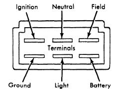
PILOT LAMP RELAY CONNECTIONS
Regulator consists of two elements constant-voltage relay and pilot lamp relay. Both relays consist of an electromagnet, contacts, frame, moving element and coil side plate. This regulator has a temperature compensation gradient as an improvement over the constant voltage charging system. It has functions for automatically compensating the adjusted value of the constant-voltage relay so that adjusted value will be lower in summer and higher in winter.
                     APPLICATION
Model                                         Part No.
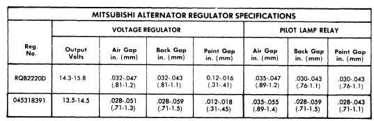
Dodge Colt   ..............................   RQB2220D
For Courier   .............................   N/A
Mazda   ....................................   0453 18 391

TESTING
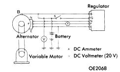
To check adjusted value of constant voltage relay, connect a voltmeter between terminal "A" and "E" of
the regulator. Place generator or no load by disconnecting one of the battery terminals during operation at idling speed, then increase alternator speed to approximately 4000 RPM (Approximately 2000 engine RPM). In this condition, satisfactory voltage is 14.0 - 15.8 volts.

ADJUSTMENT
Adjust voltage of the constant voltage relay be bending end of coil side plate up or down as shown in illustration. If plate is bent up, the adjusted valve becomes higher. If it is bent down, value becomes lower. Adjust pilot lamp relay by some method.


Hitachi Alternator Regulator 1963-74

For:

  • Datsun (1966-73)
  • Honda (1971-72)
  • Chevrolet LUV (1972-73)
  • Subaru (1971-73)
DESCRIPTION
The regulator system consists basically of a voltage regulator and a charge relay. The voltage regulator has two sets of contact points, a lower set and upper set, to control alternator voltage. An armature plate placed between the two sets of contacts moves upward, downward or vibrates. The lower contacts, when closed, complete the field of circuit direct to ground. The upper contacts, when closed, complete field circuit to ground through a resistance (field, coil), and thereby produces alternator output. The charge relay is similar in construction to voltage regulator. When upper contacts are closed, ignition warning lamp goes on.

                                   APPLICATION
Model                                                     Hitachi Part No.
Datsun
   1200
      1971-72   .............................................   TL1Z-37
      1973   ..................................................   TL1Z-57
   510
      1968-71   .............................................   TL1Z-17
      1972-73   .............................................   TL1Z-57
   521
      1969-71   .............................................   TL1Z-17
      1972   ..................................................   TL1Z-57
   520
      1966-71   .............................................   TL1Z-10
   610
      1973   ..................................................   TL1Z-58
   620 
      1973   ..................................................   TL1Z-57
   240Z
      1970-71   .............................................   TL1Z-37
      1972-73   .............................................   TL1Z-57
   Honda
      1971-72   .............................................   TL1Z-33
   Chevrolet LUV
      1972-73   .............................................   TL1Z-66
   Subaru
     1100
         1971   ...............................................   TL1Z-27
     1300
         1971   ...............................................   TL1Z-54
         1972-73   ..........................................   TL1Z-65
     1400
         1972-73   ..........................................   TL1Z-65

TESTING
VOLTAGE REGULATOR
1) Connect voltmeter and ammeter as illustrated. Start and maintain engine speed or 2500 RPM for a
VOLTAGE REGULATOR TEST CIRCUIT
few minutes, then check to make sure that reading of ammeter is 5 amps or less. If ammeter remains higher than 5 amps, disconnect battery in use and connect a battery known to be fully charged. Recheck to be sure reading of ammeter is lower than 5 amps.
2) Lower engine speed to idle and again increase it gradually to 2500 RPM, then note voltmeter reading. Function of regulator is normal if measured value is within specified regulating voltage. If reading o voltmeter deviates from specified range, it indicates regulator is in need of adjustment.


CHARGE RELAY
Set up test circuit as illustrated and check specifications table to ensure proper operation of relay
TESTING CHARGE RELAY


ADJUSTMENT
1) Disconnect and remove voltage regulator from vehicle. If contact points are roughened, smooth with fine sand paper. Check and adjust gaps, core gap first, then point gap.
NOTE - Adjustment of yoke gap is necessary on some models.
2) Adjust core gap by loosening screws attaching contact set to yoke. Move contact set upward or downward as required. Adjust point gap by loosening screw attaching upper contact. Move upper contact up or down as required to set gap to specification.
3) Adjust regulated voltage by means of adjusting screw. Turn screw in to increase regulated voltage or out to decrease voltage. When correct voltage adjustment is obtained, secure with lock nut. When adjustment procedure is complete reinstall regulator and perform on car check.


Friday, August 23, 2013

Fiat 124 Alternator Regulator 1963-74 Wiring Diagrams

CHANGES, CAUTIONS, CORRECTION

  • SERVICE PRECAUTIONS - When replacing regulator, and during bench testing, be careful not to exchange the wire to plug "15" with wire to plug "67" (see illustration). Current passing through contacts would be high enough to melt second stage contacts before fuse in lead "15" would blow..
  • HANDLING - During installation, removal, and handling protect regulator from blows which might damage the resistors and upset adjustments.
  • GROUNDING - During checks on vehicle and on bench, see that regulator is well grounded. If grounding is poor or open, alternator voltage will rise to an abnormally high value, which may damage battery and electrical equipment
  • CAPACITORS - NEVER install radio raise suppressor on regulator plug "67" as operation of contacts will be adversely affected.
  • COVER GASKET - Should gasket require replacement, use only a gasket of some original material. Unsuitable gasket could release harmful volatile substances into regulator which will foul countacts.
  • SUPPLY CIRCUITS - DO NOT connect electrical accessories directly in circuit between alternator and voltage regulator (i.e., cable between terminal "30" of alternator ignition switch plug "15" of regulator, or cable between ignition switch and voltage regulator), since alternator voltage would rise and affect life of battery and electrical equipment.
FIAT VOLTAGE REGULATOR

DESCRIPTION
For voltage regulators are of the dual stage vibrating contact type. An induction auxiliary coil, considerably smaller of the yoke. In addition to two regulating resistors, and additional resistor works in series with main voltage coil. The regulator is grounded through the mounting flanges. Resistors are protected from impacts by a metal shield secured to mounting flange.

SPECIFICATIONS
Application                                                       Data
First Part No. ................................................   RC 2/128
Alternator Test RPM.......................................   5000
1st Stage Testing (Amps)................................   25-35
2nd Stage Testing (Amps)...............................   2-12
2nd Stage Testing (Volts)................................   14.2±.3
Resistance Values (Ohms)
     Plug "15" & Ground...................................   28±2
     Plug "15" & "67 W/ Con. Open....................  5.65±.3
Armature Air Gap (In.)...................................   .069±.0028

TESTING
BENCH TESTING
1) Install alternator and regulator on test bench equipped with gradual speed control. Connect anmeter, voltmeter, and rheostat as shown in illustration. Regulator must be placed vertically, with terminals ""15" and "67" at base. Regulator must be checked without removing cover.
2) CAUTION - DO NOT operate regulator with switch "1" open (battery disconnected) since this will damage regulator contacts. Operate voltage regulator in an ambient temperature of 122±5.4° for 30 minutes (thermal stabilization). Start with rheostat fully inserted, then adjust current output to one sixth of maximum alternator output. Alternator should be operated slowly at first and then be SLOWLY brought up to 5000 RPM.
3) NOTE - Suitable thermostatic equipment must be available in order to maintain regulator at specified temperature throughout test. Operate alternator at 5000 RPM. Adjust rheostat for specified current output. See specifications.
4) Check first stage immediately after second stage, and after ensuring the same conditions of output, speed, etc. At 5000 RPM, adjust rheostat until current ouput listed (C) is obtained. See Specifications. Regulate voltage should be .2-.7 volt less than the voltage recorded above for the second stage. NOTE -  When testing the first and second stages, check that regulated voltage is stable, without any sudden surges or drops.
BENCH TEST CIRCUIT


ADJUSTMENT
NOTE - Ambient temperature must be 122±5°F.
1) With alternator stationary and switch "I" open (see illustration), remove regulator cover. If testing showed a regulated voltage higher than specified, lower the spring pressure on regulator by bending bracket on yoke up a little.
2) Conversely, if recorded regulated voltage is lower than specified, bend bracket down a little to load spring with more pressure.
3) Install cover and repeat testing of second stage. After obtaining correct setting of second stage, check first stage as directed under testing. If voltage value of first stage is .2-.7 volt less than the voltage recorded for the second stage, the adjustment is finished. Otherwise, one of the two cases may occur.
Voltage Too High - In this case, reduce armature air gap by bending down the first stage stationary contact bracket .004-.008" (.1 - .2 mm). Restore original clearance between second stage contacts .018±.004" (.45±.1 mm).
Voltage Too Low - In this case, increase armature air gap by bleeding the first stage stationary contact carrier bracket up .004-.008" (.1-.2 mm). Restore original clearance between second stage contacts .018±.004" (.45± .1 mm). Be careful to maintain centered and aligned contacts to both stages during these operations. Install cover and check regulator setting (both first and second stages); if necessary repeat specified adjustment operations until final setting is obtained.
CAUTION - Clean cover of any trace of dust, grease, moisture, etc., before installation. To prevent any possibility of moisture being trapped in regulator, cover must be mounted while unit is still warm.

A
CHARGING SYSTEM SHOWING REGULATOR INTERNAL

Wednesday, August 21, 2013

Bosch Alternator Regulators 1963-74 Models

For:

  • Alfa Romeo
  • Audi
  • BMW
  • Cabpri
  • Fiat
  • Mercedes-Benz
  • Opel
  • Porsche
  • Saab
  • Volkswagen
  • Volvo
DESCRIPTION
Bosch alternator regulators are two contact, single field units. The field coil of the alternator is grounded and voltage contacts of the regulator are in series with the field

TESTING
ON CAR TEST
Install a battery post adapter at the positive post of the battery. Connect voltmeter across the battery. Connect a tachometer to ignition system. Make sure all electrical accessories are turned off. Start engine with battery post adapter switch closed; open switch as soon as engine is started. With engine speed at 2500 RPM, load system with a 1/4 ohm resistance. After voltage reading stabilizes, any reading between 13.5 and 14.8 volts is satisfactory
BOSCH  ALTERNATOR REGULATOR


ADJUSTMENT
If voltage reading is out of limits, remove regulator cover and adjust voltage regulator armature spring tension to obtain a middle reading of 14.0 volts. If reading fluctuates, voltage contacts are dirty. Replace regulator cover and recheck voltage setting. A steady voltage reading between 13.5 and 14.5 volts indicates regulator is in good condition.