Showing posts with label Volvo. Show all posts

Saturday, January 3, 2015

Bosch Alternators 1974

Car Manufacturers Covered:

  • Alfa Romeo
  • Audi
  • BMW
  • Capri
  • Fiat 128 & X1/9
  • Mercedes-Benz
  • Opel
  • Porsche
  • Saab
  • Volkswagen
  • Volvo 4 Cylinder
CHANGES, CAUTIONS, CORRECTIONS
BATTERY INSTALLATION, BATTERY CHARGING, OR USING A BOOSTER BATTERY TO START ENGINE - Reversed polarity or excessive voltage will result in damage to alternator system. Note the following to prevent damage:
Battery Installation - Negative battery terminal must be connected to ground. Positive terminal must be connected to starter lead. DO NOT reverse battery leads.
Battery Charging - If a Quick Charger is used, both battery cables must be disconnected from the battery. DO NOT use a Quick Charger to provide starting voltage.
Booster Battery (For Engine Start) - Booster battery must be connected with negative lead to negative terminal of battery and positive lead to positive terminal of battery. DO NOT reverse battery leads.
                                   APPLICATIONS
Model                             Type No.                          Part No.
Alfa Romeo ................ K1 14V 45A 22 ............. * 0 120 400 848
Audi .................................. ... ............................. ** 059 903 017D
BMW
     2002, 2002A .......... K1 14V 45A 22 ............. * 0 120 400 752
     2002 tii ................... K1 14V 45A 22 ............. * 0 120 400 794
     3.0 .......................... K1 14V 45A 20 ............. * 0 120 400 702
Capri
     4 Cyl. W/A.C ............... ... .............................. *** D4RY-C
     4 Cyl. All Others ......... ... .............................. *** D4RY-B
     V6 W/ A.C. .................. ... .............................. *** D4RY - D
     V6 All Others .............. ... .............................. ***D4RY-A
Fiat 128 & X1/9 ................ ... ............................. * 0120 300 568
Mercedes Benz
     230, 240D .................... ... .............................. **** 0041 546 902
     280 ........................ K1 14V 55A 20 .............. **** 0041 541 802
     450 ........................ K1 14V 55A 20 .............. **** 0031 545 602
Opel ................................ ... ................................ * 0 120 400 620
Porsche
     4 Cyl .......................... ... ................................ ***** 022 903 023
     6 Cyl .......................... ... ................................ *****911 603 118 00
Saab
     99 .............................. ... ................................. *0120 400 850
     V4 ............................. ... .................................  *0120 400 657
Volkswagen 
     Type 1 ........................ ... ................................ * 0120 400 836 or 862
     Type 2 & 4 ................. ... ................................ * 0120 400 721
     Dasher ........................ ... ................................ * 0120 489 532 or 535
Volvo 
     140 ............................. ... ................................ * 0120 400 756
     164 ............................. ... ................................ * 0190 601 011
* - Bosch Part No.
** - Audi Part No.
*** - Motorcraft Part No.
**** - Mercedes Benz Part No. 
***** - VW Part No.
DESCRIPTION
Bosche alternators are conventional three-phase, self-rectifying type alternators. Nine rectifier diodes are connected to the stator windings (three to each phase lead). The diodes change the alternator A.C. voltages to D.C. voltages coming out of the "B+" and "D+" terminals of the alternator.
                                  SPECIFICATIONS
Alternator*                     Amp Output @ RPM                     Max Current
G1 14V 33A 27 ...................  33 @ 5000 ................................... 40A
K1 14V 35A 20 ................... 23 @ 2000 .................................... 35A
K1 14V 45A 20 .................... 30 @ 2000 ................................... 45A
K1 14V 45A 20 .................... 30 @ 2200 ................................... 45A
K1 14V 50A 20 .................... 33 @ 2000 ................................... 50A
K1 14V 55A 20 .................... 36 @ 2000 ................................... 55A
K1 14V 55A 22 .................... 36 @ 2200 ................................... 55A
* - Charging voltage: 14.
Field Coil Resistance - 4.0 ohms + 10% measured at slip rings at normal ambient temperature.
Stator Windings Resistance - .2 ohms + 10% measured between the phase output terminals
ON VEHICLE TESTING
NOTE - Off vehicle testing is explained as part of Overhaul procedure in this article.
WIRING CONTINUITY TEST
Disconnect terminal plug from rear of alternator and connect a voltmeter negative terminal to ground. With Ignition "ON", connect positive lead to each of  the connector wires, in turn. Voltmeter should read battery voltage as each positive connection is made. If proper voltage is not read, trace each wire to find fault.
VOLTAGE DROP TEST - GROUND SIDE
Connect voltmeter between negative terminal of battery and alternator housing. Start engine and run at approximately 3000 RPM. If voltmeter reading exceeds .25 Volts, a high resistance in negatvie side of charging circuit is indicated. If so, check for loose, dirty, or corroded connections.
OUTPUT TEST
Disconnect terminal plug from rear of alternator and connect ammeter, in series between alternator center terminal and corresponding socket in terminal plug. Also connect a jumper lead between the "D+" terminal and its corresponding socket in terminal plug. Start engine and run at approximately 3000 RPM. Turn on headlights and leave on for five minutes. Ammeter should read maximum alternator amperage at normal operating temeperature.
REGULATOR CONTROL VOLTAGE TEST
Connect a voltmeter between main terminals of battery. Connect an ammeter, in series, between "B+" terminal of alternator and corresponding terminal of connector plug. Connect a jumper lead between alternator "D+" terminal and corresponding terminal of connector plug. Start engine and increase speed to approximately 3000 RPM. Run engine until charging rate falls below 10 amps. The voltmeter should then read 14.1 - 14.4 Volts. If these readings are not obtained, replace regulator.
NOTE - The test cables should not be removed or the load excessively reduced during the diodes. The control lamp should not go on at any time during the test.
BOSCH ALTERNATOR (TYPICAL)

OVERHAUL
DISASSEMBLY
NOTE - On 0 120 400 600 series alternators, lift carbon brushes with hook and secure them, prior to disassembly (see illustrations).
1) Remove nut, pulley, hub and key. Mark location of alternator in blower housing. Unscrew brush
LIFTING CARBON BRUSHES
(0 120 400 600 Series)
plate assembly and remove from alternator. Remove bolts from end frame, then remove frame and field rotor. Press rotor out of end frame. Press ball bearing off rotor. Remove insulating conduit from wires and cut wires as close to soldered joints as possible.
2) The diodes may be tested at this point, prior to further disassembly. Care should be exercised with insulating busings under positive diode carrier. To remove negative carrier, extract threaded studs. When one rectifying diode has been damaged due to short circuiting, the three complementing diodes must be replaced also. Unscrew nuts on both "B+" terminal bolts and lift positive diode carrier (heat sink) up and back.
TESTING & REPAIRING
Diode Assemblies - test diodes with a suitable alternator tester (EFAW 192) before dismantling slip ring end frame further. CAUTION - Do not lay positive diode carrier on housing or false reading will be obtained. Disconnect conductor from "D+" to the exciter diodes at the exciter diodes heat sink. Unscrew spring and brush holder and remove from alternator. Unsolder stator lead and negativediode connection. Unscrew exciter diodes heat sink  and remove together with positive diodes heat sink.
NOTE - Before further testing, lightly clean all components in gasoline or trichlorethylene, but do not soak.
Stator - Test stator for short circuits to ground, using suitable tester (EFAW 84). Test voltage should be 40V AC. Measure resistance of stator windings between phase connections. See specifications for proper value.
Rotor  - 1) Test claw pole rotor for short circuits to ground. Test voltage should be 40V AC. Measure resistance of exciter (field coil) in rotor with ohmmeter. See Specifications for proper value. Turn down slip rings on a lathe, using suitable tailstock chuck (EFAW 75 or GDF 85 R 3).
2) After turning, check concentricity of slip rings with dual gauge. Runout should not exceed .001" (.03 mm). Minimum diameter of slip rings may be 1.25" (31.5 mm). Maximum runout of pole wheel must not exceed .002" (.05 mm).
Diode Replacement - 1) On all except 0 120 400 600 series alternators, set diode plate on press die and force diodes out with plunger. Place diode plate (without diodes) onto suitable guide pilot (EFLJ 57/0/5) and set diode seat with suitable sleeve (EFLJ 57/0/3). Smear silicone oil on diode seat, place diode palte on press die and press diodes into position. After pressing in, test all diodes.
2)  On 0 120 400 600 series alternators, set slip ring end frame on press die and force out defective diode. Coat diode seat with silicone oil and press in new diode. Test all diodes after replacement.
Drive End Frame - Check ball bearings for wear and replace as necessary. Lubricate bearings on one side. Press ball bearing into drive end frame with shielded side downward. Screw on retainer plate. Press ball bearing onto rotor (slip ring end), then press drive end frame onto rotor.
Carbon Brushes - Unsolder and replace carbon brushes. Do not allow solder to run into copper stands of brush leads. Minimum brush length is .55" (14 mm). After installation of new brushes, test for free movement.
REASSEMBLY & TESTING
1) On all except 0 120 400 600 series alternators (steps 1 through 4), fit negative diodes heat sink and clamps. Screw in double end bolts (shorter threads outward). NOTE - Left clamp is longer than right. Replace insulating washers and bushings. Test terminal bolt "B+" for short circuit to ground. Test voltage should be 80V AC.
2) Position positive diodes heat sink (carrier) and secure with insulating and spring washers. NOTE -
INSTALLATION OF DIODES
Use insulating cap NO. 1 120 502 000 instead of insulating washer on bolt nest to terminal marked "D+/61".
Tighten hex nuts.
3) Place stator in slip ring end frame. Draw positive and negative diode leads together and lip through an insulating sleeve. Push sleeve over lead of exciter diode and stator connections cable. Crimp a metal ring around end of leads and solder. Cut off any excess wire protruding through ring. Reposition wiring and attach in holding clamps.
4) Side insulating sleeve over exciter diode terminal. Insulating sleeves of stator connection lead must  project over edge of negative diodes heat sink. Clamp connections firmly. 
5) On 0 120 400 600 series alternators (step 5 through 7), test both "B+" terminal bolts for short circuit to ground. Test voltage should be 80V AC. Before fitting exciter diodes heat sink (carrier), solder three positive diode terminal leads onto heat sink from below.
6) After fitting exciter diodes heat sink, solder stator leads, negative and exciter diodes to the "COMB". NOTE - Use caution, do not overheat negative diodes. Install brush holder. Raise and secure carbon brushes before installing. Screw conductor "D+" onto exciter diodes heat sink.
7) Place wave spring washer into ball bearing fit. Rub ball bearing seat with suitable lubricant. Insert rotor with drive end bearing into slip ring end frame and secure. Springs are to be set onto carbon brushes by pressing on brush with a screwdriver. Brush spring pressure will seat brushes automatically.
8) Rub suitable lubricant into ball bearing seat of slip ring end frame. Install claw pole rotor with drive end frame. Check position of stator relative to end frame. Position brush holder plate. Tighten screws. Install fan belt pulley. Coat newly installed positive diodes with chlorinated rubber lacquer.

Monday, June 2, 2014

S.E.V. Motorola Alternators 1968-73

  • Renault (1969-73)
  • Simca (1969-70)
  • Volvo (1968-73)

CHANGES, CAUTIONS, CORRECTIONS
BATTERY INSTALLATION & OTHER ELECTRICAL REPAIRS CAUTION - Reverse polarity or excessive voltage will result in extensive damage to alternator system. Note the following to prevent damage:
Battery Installation - Negative battery terminal must be connected to ground (negative ground system) and positive terminal must be connected to starter. DO NOT reverse battery leads.
Battery Charging - If a Quick Charger is used, both battery cables must be disconnected from the battery. DO NOT  use a Quick Charger to provide starting voltage.
Circuit Interruption - The battery must NEVER be disconnected while alternator is running.
Alternator Removal - Always disconnect battery ground before replacement of alternator.
High Voltage - DO NOT use a high voltage source to test diodes.
Booster Battery (For Engine Start) - Booster battery must be connected with negative lead to negative battery terminal and positive lead to positive terminal. DO NOT reverse battery leads.
Field Terminal - NEVER ground field energizing terminal on alternator, regulator, or connecting lead.
Voltage Regulator - NEVER operate voltage regulator without a good ground connection or immediate damage will result.
DESCRIPTION
SEV Motorola alternators are conventional three-phase, self rectifying type alternators. Six silicone diodes (three positive and three negative) are used to rectify AC currrent. The 35 ampere alternator use one isolation diode mounted in a heat sink attached to end frame. The 55 ampere unit incorporates two isolation diodes (connected in parallel) which are mounted on exterior. Isolation diodes (when used) have two functions: They prevent battery from discharging through regulator and alternator field, and they provide a simple means of operating charge warning lamp.
             APPLICATION
Model                           *Part No.
Renault
   R-12
      1971-72.....................7122-8302
      1973.....................77 00 559 308
   R-15
      1972-73...............77 00 532 831
   R-16
      1969-70....................** A 12/30
      1971-72...............77 00 500 295
   R-17
      1972.....................77 00 529 484
      1973.....................77 00 559 309
Simca
   1204
      1969-70..................*** S 34266
Volvo
   140 Series
      1968-71.....................14V-26641
      1972................................419420
      1973...................................33525
   164
      1969-71.....................14V-34833
      1972.................................419420
      1973...........................14V-34833
   1800
      1972.................................460085
      1973...................................33525
* - Each number listed is either Renault part number, Simca part number or Volvo part number.
** - Type Number.
*** - Standard, optional part number is S 30479
SPECIFICATIONS
                           Nominal Output
Application          Amps. @ RPM         Volts
7122-8302..................30 @3000.............13.2
77 00 559 308............30 @ 3000.............13.2
77 00 532 831............30 @ 3000.............13.2
A 12/30......................35 @ .... ................. ....
77 00 500 295............. ............ ................13.2
S 34266....................... ........... ................. ....
14V-26641.................35  ... .......................13
419420.......................35 @ 5000.............14.2
33525.........................48 @ 3000.............13.2
14V-34833.................48 @ 3000...............14
460085.......................55 @ 4000...............14
* - Charging Voltage
                       Coil Resistance (Ohms)
Application               Rotor                  Stator
7122-8302.................5.2......................... *
77 00 559 308...........5.2......................... *
77 00 532 831...........5.2......................... *
A 12/30.....................5.2......................... *
77 00 500 295........... ... ......................... ..
77 00 529 484........... ... ......................... *
77 00 559 309...........5.2......................... *
S 34266..................... ... ......................... ..
14V-26641................5.2......................... *
419420......................5.2......................... *
33525........................3.7......................... *
14V-34833................3.7......................... *
460085......................3.7......................... *
* - See stator testing in Overhaul.
TESTING
ON CAR TEST
Connect alternator as shown in illustration, Check that current through field winding (rotor) is 3.5 amps. If
ALTERNATOR TESTING CIRCUIT
current is not 3.5 amps, check field winding condition and brush holder. Run engine speed to 3000 RPM. Alternator should then produce the specified current. Measure voltage at terminal "B+" and at terminal "61". Voltage should be .8-.9 volts more at terminal "61". If not, isolation diodes are faulty and should be replaced.
OVERHAUL
DISASSEMBLY
1) Release two screws holding brush holder and remove isolation plate (if equipped). Pull out brush holder.
2) Hold pulley with belt in a vise with soft jaws, and remove the nut and washer. Lift off pulley, fan, key and spacer washer.
3) Remove nuts and washers on terminal 61 and the corresponding terminal on the other side of isolation diode. Mark drive shield, stator and slip ring end shield for correct reassemly position.
CHECKING BRUSH HOLDER
4) Remove four attaching screws. Remove rotor and drive end shield with help of two screwdrivers, which are inserted in two sockets between stator and drive end shield. CAUTION - The screwdrivers may not be inserted deeper than 1/14" (2 mm) otherwise stator may be damaged.
5) Release three screws holding support plate of drive end bearing. Release bearing by knocking end of shaft against a piece of wood.
6) Remove nuts and washers for the diode holder for negative diodes. Remove stator and diode holders for slip ring end shield.
S.E.V. MOTOROLA ALTERNATOR (TYPICAL)

TESTING
Stator - Check stator for short-circuiting. If one or more of the coils are burned, there must be a short-circuit in stator. Connect test lamp (12 volt, 2-5 watt) between stator plates and terminal on stator (see illustration). If lamp lights, isolation between stator winding and stator plates must be burned, in which case stator should be replaced. NOTE - Use only test lamp as specified. DO NOT use a 110-volt or 220-volt test lamp on this or any alternator test procedure
STATOR CHECK
Diodes - Check diodes with a diode tester. If any of the rectified diodes are shorted or open, the diode holder must be replaced. If any isolation diode is faulty, replace holder, complete with isolation diodes. If diode tester is not available, diode should be unsoldered and tested with an ohmmeter. Diodes should show high resistance in reverse direction and low resistance in flow direction.
Rotor - Check to make sure slip rings are not dirty or burned. Check winding for breakage or damage isolation. Measure resistance between slip rings. It should be as specified. If winding is faulty, rotor must be replaced. NOTE - It is recommended that bearings be replaced whenever alternator is disassembled.
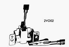
Brush Holder - Connect a test lamp between the brushes. Lamp should not light. Next connect test lamp between "DF" terminal and the "+" brush. Lamp should give steady light even if brush or terminal cable is moved (see illustration). Connect test lamp between brush holder frame and "-" brush. Lamp should give steady light. If test results are not satisfactory or brush length is less than 3/16" (5 mm), replace brush holder. NOTE - Brush length is measured between brush contact surface and holder, with brush resting against spring.
PARTS REPLACEMENT
Diodes - Mark leads connecting stator to diodes, then unsolder leads. Place new diode holder in exact position of holder being replaced. Solder new leads, holding with pliers (this is to conduct heat from soldering point, to avoid damaging new diode). Use a minimum 100-watt, well-heated soldering iron. Never change places of diode holders. Positive holder is isolated from frame by means of isolation washers and sleeves and its diodes are marked in red. Negative diode holder is not isolated and its diodes are marked in black.
REASSEMBLY 
Alternator is reassembled by reversing order of disassembly, noting the following: Rotor must be pressed into drive end shield. Connect a test lamp between "B+" terminal and alternator frame, then reverse connections. Lamp should light only in one direction. After completion of reassembly, test run alternator on bench, using same procedure as described for On Car Testing.

Wednesday, September 5, 2012

Volvo 240 260 Series 1975-77 Drive Axles Repair Guide

Models Covered
  • 240 Series
  • 260 Series 
DESCRIPTION
Rear axle assembly uses a hypoid type ring gear and pinion gear set. Semi-floating axle shafts are retained in housing by tapered roller bearings and a bearing retainer at housing outer ends. Bearing clearance is not adjustable and is determined by bearing design. Differential adjustment is accomplished by the use of shims.
AXLE RATIO & IDENTIFICATION
A plate attached on left side of axle housing gives axle ratio part number, and serial number.
REMOVAL & INSTALLATION
AXLE SHAFT & BEARINGS
1) With vehicle raised and wheels removed, disconnect brake line from caliper. Remove disc and caliper. Loosen bolts for thrust washer through holes in axle flange. Pull out shaft using suitable puller. Remove inner sealing ring using a puller or by prying it out with a screwdriver.
2) Press bearing and lock ring off axle shaft using suitable tools. Remove oil seal. Fill space between new seal lips with grease, then install seal on axle shaft. Install bearing and new lock ring by pressing on axle shaft. Always use a new lock ring and insure that bearing is installed with taper away from axle shaft flange.
3) Use a suitable seal installing tool and install inner seal ring. Fill bearing with good quality grease. Also fill space between seals and between seal lips with grease. Install axle shaft and tighten thrust washer bolts. Install brake disc and caliper, reconnect brake line, bleed and adjust brakes. Install road wheels and lower vehicle
PINION FLANGE & SEAL
1) Disconnect rear section of propeller shaft from pinion flange. Check for looseness of pinion in its bearing. If it is loose, this must be remedied before a new oil seal is installed. Remove nut from flange using suitable flange using suitable flange holding tool. Pull off flange using suitable puller. Pull out old oil seal.
2) Coat seal lip of new ring with grease. Also lubricate the spring coil so it does not jump off during installation. Install oil seal using suitable seal installing tool. Press on flange using suitable pressing tool. Install flange washer and nut and tighten. Reconnect propeller shaft.
AXLE ASSEMBLY
1) With rear of vehicle raised and supported and wheels removed, support rear axle with suitable jack and holding fixture. Remove upper attaching bolts for shock absorber and parking brake cables from levers and brackets on brake backing plate. Remove propeller shaft from pinion flange and remove pipe union from rear axle housing.
2) Disconnect Panhard rod from bracket on rear axle housing and remove lower attaching bolts for spring. Lower jack until trailing arms release from spring. Loosen bolts holding rear axle housing to trailing arms. Lower jack and pull rear axle assembly forward.
3) To install, move axle under vehicle and install bolts for support arms and torque rod. Raise jack until Panhard rod can be installed. Install attaching bolts for spring and tighten nuts for support rods and trailing arms. Install bracket, union, and brake hoses. Reconnect propeller shaft to pinion flange. Install upper bolt for shock absorbers and reconnect parking brake cable. Adjust parking brake and bleed brakes. Install wheels and lower vehicle
OVERHAUL
DISASSEMBLY
1) Place axle assembly in suitable holding fixture with pinion flange pointing downward. Remove brake lines and axle shafts. Remove inspection cover. If final drive is being reconditioned because of noise, run a tooth contact pattern check before disassembly as this may assist in locating fault.
2) Check alignment marking on bearing caps and carrier. If there are no marking, or if they are difficult to see, mark one side with a punch. Remove cap. Using a suitable case stretching tool, lift out carrier with ring gear. Turn final drive over and drain oil. Remove pinion flange and press out pinion. Remove pinion front bearing washer and oil seal with a suitable driver.
3) If necessary, drive out rear pinion bearing from case using a suitable drift. Clean axle case gasket surface and remove any burrs present. If necessary, pull of rear bearing from pinion using a suitable puller. Pull off differential carrier bearing with suuitable puller and retain shims. Remove lock plate for ring gear bolts, remove bolts and ring gear. Drive out lock pin securing differential gear and remove shaft, gears and thrust washers.
Fig. 1 Exploded View of  Volvo Drive Axle Assembly

INSPECTION
Fig. 2 Pinion Adjusting Ring & Tool
Inspect all parts for wear or damage. Also install differential gear into carrier together with shaft and thrust washers. Use no lubricant. Now, check play of differential side gears. If play exceeds specifications when gears have been rotated to maximum play, replace thrust washers with thicker ones.
REASSEMBLY & ADJUSTMENT
Case Assembly - Place differential side gears together with thrust washers in differential carrier. "Roll" in both side pinions simultaneously with dished thrust washers, then drive in shaft. Install ring gear, making sure that contact surfaces are clean and without any burrs. Install new ring gear bolts and tighten.
Fig. 3 Measuring Drive Pinion Gear Installed Height
Drive Pinion Depth & Bearing Preload - 1) Clean marking surface on drive pinion. Install adjusting ring tool (2685) and (2841) on pinion and place this assembly into housing. Place pinion on carrier so bolt on adjusting ring faces large side of carrier.
2) The pinion should have a certain nominal measurement to the center line of the ring gear. Due to manufacturing tolerances, there are deviations from this nominal measurement.  On rear axles made by Volvo, the deviation is always positive and is indicated hundredths of a millimeter. The plus sign is excluded.
3) Place pinion gauge (2393) on ground surface of pinion and adjusting jig (2393) in differential bearing positions. Place dial indicator retainer (2284) with dial indicator on gasket face of axle housing with dial indicator foot touching adjusting ring. Zero dial indicator. Now move indicator over until it touches pinion gauge. If the pinion is, for example, marked 33, the pinion gauge should lie .013" (.33 mm) under adjusting fixture. The setting is adjusted by turning cam on pinion until dial indicator shows correct value, then lock adjusting ring with set screw.
Fig. 4 Zeroing Dial Indicator
4) Remove measuring tool and pinion. Place complete rear pinion bearing with outer ring in measuring fixture (tool 2600). Put on plate, spring and nut with flat side of nut facing up. Rotate plate and bearing several times so that rollers take up correct set. Place adjusting ring in retainer (tool 2284) and dial indicator opposite adjusting ring, zero indicator. Set pointer of indicator to outer ring of bearing. The indicator will now show directly the thickness the shims should have. Measure shims for correct thickness with micrometer. Since it is unlikely to find a shim  with the exact thickness required, shim may be .0012" (.03 mm) thicker or .002" (.05 mm) thinner than measured value.
5) Press rear bearing on pinion with suitable sleeve. The washer under rear bearing inner ring must NOT be installed when overhauling. Place measured shims in axle housing and press in both outer rings of bearings using suitable tool. Insert pinion in housing and install three .03" (.75 mm) thick shims and front pinion bearing. Pull pinion into housing using suitable tool. Install washer and nut on pinion shaft and tighten to specifications.
Fig. 5 Measuring Installed Depth of Pinion Gear
6) Install pinion gauge and dial indicator retainer. Pull down pinion while rotating it backwards and forwards. Set dial indicator to zero. Press pinion upwards while rotating it forwards and backwards. Dial indicator will read clearance.Remove pinion and remove shims corresponding to the measured clearance plus .003" (.07 mm). Reinstall pinion. Now use torque gauge to check pinion bearing torque. Adjust shim thickness if required to obtain specified torque. Recheck pinion depth using measuring tools as described in step 3.
Backlash & Side Bearing Preload - 1) Lubricate inside of adjustment rings (tool 2595) and install then on differential carrier. Ring with block oxidized adjustment ring should be placed on ring gear side. Also lubricate bearing bores in carrier. Install carrier and adjustment rings in axle housing.
2) Use dial indicator and adjust ring so that specified backlash is obtained. Backlash may vary within backlash range but get as closer to specified backlash as possible.
Fig. 6 Determining Pinion Depth Shim Thickness
NOTE - Due to altered manufacturing and test procedures, it is no longer possible to determine correct installation of gears by means of a contact pattern test. The pinion gear should always be installed in its marked position regardless of the contact pattern.
3) If the gear set is correctly installed, but still causes noise, try re-positioning the pinion gear .002 (.05 mm) plus or minus (try plus first). This may help if the pinion gear has been incorrectly marked.
4) After correct backlash is obtained, remove carrier and adjustment ring. Place adjusting ring and bearing into measurement fixture with flat side of nut facing downwards. Rotate plate several times. Install dial indicator and retainer tool (tool 2284) and zero indicator on adjusting ring. Place measuring point of indicator facing bearing and read off indicator.
5) Use a micrometer to form a shim pack equal in thickness to clearance indicated by dial indicator plus .003" (.07 mm). Place shims together with measured bearing to one side. Repeat this procedure with the other bearing. Install shims on differential carrier, making sure which side respective bearing and shims are installed on, and press on bearings using suitable drift. When installing second bearing, use suitable support so as not to damage first bearing.
NOTE - Do not forget to lock cover for ring gear bolt.
6) Install tool (2394) on pinion carrier and expand tool until pins are flush against hole edges in carrier, then tighten screws an additional 3 1/2 turns. Install differential carrier and outer rings. Install bearings caps and tighten bolts to specification.
7) Install pinion oil seal and flange, and inspection cover and gasket. If inner oil seals for axle shafts were removed, drive them in with suitable tool. Reinstall axle shafts and adjust end play if necessary. install brake discs, caliper and brake pipes. Bleed and adjust brakes.


Volvo 1968-74 Drive Axles Repair Guide

Models Covered:
  • 120 Series (1968)
  • 140 Series (1968-74)
  • 164 Models (1969-74)
  • 1800 Series (1968-73)
DESCRIPTION
All rear axles are hypoid design with centerline of pinion set below centerline of ring gear. Semi-floating axle shafts are retained in housing by ball bearings and a bearing retainer at axle housing by ball bearings and a bearing retainer at axle housing outer ends. On 1968-69 120, 140 and 1800 series models, bearing clearance is not adjustable. On all other models, bearing clearance is not adjustable and is determined by the construction of the bearing. All adjustments are performed using shims.
AXLE RATIO & IDENTIFICATION
1968-70 Models - A plate on lower part of inspection cover shows number of teeth and axle ratio of final drive.
1971-74 - A plate on left side of rear axle housing gives axle ratio, part number and serial number of final drive.
REMOVAL & INSTALLATION
AXLE SHAFTS AND BEARINGS
1968 120 Series - 1) With vehicle raised and rear wheels removed, pull off wheel hub. Place wood block under brake pedal and remove brake line from backing plate. Use suitable puller to remove brake backing plate. Pull out axle shaft using suitable puller . Pull out oil seal and press bearing off axle shaft.
2) Press new bearing onto axle shaft and install new oil seal using suitable driver. Make sure is correctly located. Install axle shaft, shims and brake backing plate with a new felt washer. Check axle shaft end play. If not to specifications, reshim to obtain specified end play. Replace draw key if removed and install hub and wheel. Reconnect brake line, bleed and adjust brakes.
1968-69 140 & 1800 Series - 1) With vehicle raised and rear wheels removed, disconnect brake pipe from brake unit. Remove brake caliper and disc, then remove return spring for brake shoes and remove shoes. Disconnect handbrake cable from bracket and lever. Remove lever and cable. Loosen bolts for brake backing plate and brake shoe retainer. These are loosened through holes in drive shaft flange. Turn brake backing plate backwards so that handbrake bracket goes free from flange on casing. Pull out axle shaft using a suitable puller.
2) Secure axle shaft in a vise so that recess in brake backing plate is facing rear jaw of vise. Drill a 1/4" (6 mm) hole in lock ring taking care not to drill through ring into shaft. Split the ring with a chisel taking care not to damage the bearing. Loosen shaft from vise and remove ring. Using a suitable puller, remove bearing from axle. Drive out oil seal using a suitable seal driver. Clean and check all parts, especially make sure no cuttings from drilling remain as these could damage bearing.
3) Drive new oil seal in brake shoe retainer with suitable drive. Press bearing and locking ring onto axle shaft using press and suitable support tools. Pull out inner oil seal from axle housing using a suitable puller. Drive in new inner seal ring with a suitable drift. Pack bearing well with grease and then install axle shaft, brake backing plate and brake shoe retainers. Fill entire space between seals with grease. Check that axle end play is to specifications by first pressing out outer rings from bearings with help of impact hammer. Adjust if necessary by means of adjusting nut at left side. Lock adjusting nut with suitable tab.
4) Install handbrake lever, brake shoes, spring, adjusting device, and cable. Install brake disc and caliper. Bleed out adjust brakes. Install road wheels and lower vehicle.
All Other Models - 1) With vehicle raised and wheels removed, disconnect brake line from caliper. Loosen bolts for brake disc and caliper, remove disc and caliper. Loosen bolts for thrust washer through holes in axle flange. Pull out axle shaft using a suitable puller. Pull out inner sealing ring with a puller or by prying out with screwdriver.
2) Press bearing and lock ring off axle shaft using suitable tools. Remove oil seal. Fill space between new seal lips with grease, then install seal on axle shaft. Install bearing and new lock ring and insure that bearing is installed with taper away from axle flange.
3) Use a suitable seal installing tool and install inner seal ring. Fill bearing with good quality grease. Also fill space between seals and between seal lips with grease. Install axle shaft and tighten thrust washer bolts. Install brake disc and caliper, reconnect brake line, bleed and adjust brakes. Install road wheels and lower vehicle.
PINION FLANGE AND SEAL
1) Disconnect rear section of propeller shaft from pinion flange. Check for looseness of pinion in its bearing. If it is loose, this must be remedied before a new oil seal is installed. Remove nut from flange using suitable flange holding tool. Pull off flange using suitable puller. Pull out old oil seal.
2) Coat seal lips of new ring with grease. Also lubricate the spring coil so it does not jump off during installation. Install oil seal using suitable seal installing tool. Press on flange using suitable pressing tool. Install flange washer and nut and tighten. Reconnect propeller shaft.
AXLE ASSEMBLY
1) With rear of vehicle raise and supported and wheel removed, support rear axle with suitable jack and holding fixture. Remove upper attaching bolts for shock absorber and parking brake cables from levers and brakets on brake backing plate. Remove propeller shaft from pinion flange and remove brake pipe union from rear axle housing.
2) Loosen front attaching bolts for trailing arms approximately one turn. Remove rear bolts for support rods. Disconnect Panhard rod from bracket on rear axle housing and remove lower attaching bolts for spring. Lower jack until trailing arms release from spring. Loosen bolts holding until trailing arms release from spring. Loosen bolts holding rear axle housing to trailing arms. Lower jack and pull rear axle forward.
3) To install, move axle under vehicle and install bolts for support arms and torque rod. Raise jack until Panhard rod can be installed. Install attaching bolts for spring and tighten nuts for support rods and trailing arms. Install bracket, union and brake hoses. Reconnect propeller shaft to pinion flange. Install upper bolt for shock absorbers and reconnect parking brake cable. Adjust parking brake and bleed brakes. Install wheels and lower vehicle.
OVERHAUL
DISASSEMBLY
ZERO SETTING INDICATOR
1) Place axle assembly in suitable holding fixture with pinion flange pointing downward. Remove brake lines and axle shafts. Remove inspection cover. If final drive is being reconditioned because of noise, run a tooth contact pattern check before disassembly as this may assist in locating fault.
2) Check alignment markings on bearing caps and carrier. If there are no markings, or if they are difficult to see, mark one side with a punch. Remove cap. Using a suitable case stretching tool, lift out carrier with ring gear. Turn final drive over and drain oil. Remove pinion flange and press out pinion. Remove pinion fornt bearing, washer and oil seal with a suitable driver.
3) If necessary, drive out rear pinion bearing from case using a suitable drift. Clean axle case gasket surface and remove any burrs present. If necessary, pull off rear bearing from pinion using a suitable puller. Pull off differential carrier bearing with suitable puller and retain shims. Remove lock plate for ring gear bolts, remove bolts and ring gear. Drive out lock pin securing differential gear shafts and remove shaft, gears and thrust washers.
INSPECTION
PINION DEPTH MEASURING TOOL
Inspect all parts for wear or damage. Also install differential gear into carrier together with shaft and thrust washers. Use no lubricant. Now, check play of differential side gears. If play exceeds specifications when gears have been rotated to maximum play, replace thrust washers with thicker ones.
REASSEMBLY & ADJUSTMENT
Case Assembly - Place differential side gears together with thrust washers in differential carrier. "Roll" in both side pinions simultaneously with dished thrust washers, then drive in shaft. Install ring gear, making sure that contact surfaces are clean and without any burrs. Install new ring gear bolts and tighten.
Drive Pinion Depth & Bearing Preload - 1) Clean marking surface on pinion with very fine emery cloth. Install adjusting ring (tool 2685 on 140 & 1800 series or 2840 on 164 models) and tool (2841) on pinion and place in axle housing. Secure adjusting ring by screwing out lock screw on 164 models.
MEASURING PINION DEPTH
2) The pinion should have a certain nominal measurement to the center line of the ring gear. Due to manufacturing tolerances, there are deviations from this nominal measurement. On rear axle made by Volvo, the deviation is always positive and is indicated in hundredths of a millimeter. The plus sign is excluded. On other rear axles, the deviation is indicated in thousandths of an inch and with a plus or minus sign. If a plus sign is indicated, the nominal measurement is to be increased and vise versa.
3) Place pinion gauge (2393) on ground surface of pinion and adjustin jig (2393) in differential bearing positions. Place dial indicator retainer (2284) with dial indicator on gasket face of axle housing with dial indicator touching adjusting ring. Zero dial indicator. Now move indicator over until it touches pinion gauge. If the pinion is, for example, marked 33, the pinion gauge should lie .33 mm (.013") under adjusting fixture. NOTE - If the axle is not made by Volvo and pinion figure is marked minus, then pinion gauge should be higher than adjusting fixture. The setting adjusted by turning cam on pinion until dial indicator shows correct value, then lock adjusting ring with set screw.
DETERMINING SHIM THICKNESS
4) Remove measuring tool and pinion. Place complete rear pinion bearing with outer ring in measuring fixture (tool (2600). Put on plate, spring and nut with flat side of nut facing up. Rotate plate and bearing several times so that rollers take up correct set. Place adjusting ring in retainer (tool 2284) and dial indicator opposite adjusting ring, zero indicator. Set pointer of indicator to outer ring of bearing. The indicator will now  show directly the thickness the shims should have. Measure shims for correct thickness with micrometer. Since it is unlikely to find a shim with the exact thickness required, shim may be .0012" (.03 mm) thicker or .002" (.05 mm) thinner than measured value.
5) Press rear bearing on pinion with suitable sleeve. The washer under rear bearing inner ring on a Volvo rear axle must NOT be installed when overhauling. Place measured shims in axle housing and press in both outer rings of bearings using suitable tool. Insert pinion in housing and install three .03" (.75 mm) thick shims and front pinion bearing. Pull pinion into housing using suitable tools. Install washer and nut on pinion shaft and tighten to 200-220 ft. lbs. (28-30 mkg).
6) Install pinion gauge and dial indicator retainer. Pull down pinion while rotating it backwards and forwards. Set dial indicator to zero. Press pinion upwards while rotating it forwards and backwards. Dial indicator will read clearance. Remove pinion and remove shims corresponding to the measured clearance plus .003" (.07 mm). Reinstall pinion. Now use torque gauge to check pinion bearing torque. Adjust shim thickness if required to obtain specified torque. Recheck pinion depth using measuring tools as described in step 3.
Backlash & Side Bearing Preload - 1) Lubricate inside adjustment rings (tool 2595) and install them on differential carrier. Ring with black oxidized adjustment ring should be placed on ring gear side. Aslo lubricate bearing bores in carrier. Install carrier and adjustment rings in axle housing.
2) Use dial indicator and adjust rings so that specified backlash is obtained. Backlash may vary within backlash range but get as close to specified backlash as possible. Perform a contact patter test on unit. Adjust pinion depth as necessary to obtain correct pattern. Remove carrier and adjusting ring. Place adjusting ring and bearing into measurement fixture with flat side of nut facing downwards. Rotate plate several times. Install dial indicator and retainer (tool 2284) and zero indicator on adjusting ring. Place measuring point of indicator facing bearing and read off indicator.
3) Use a micrometer to form a shim pack equal in thickness to clearance indicated by dial indicator plus .003" (.07 mm). Place shims together with measured bearing to one side. Repeat this procedure with the other bearing. Install shims on differential carrier, making sure which side respective bearing and shims are installed on, and press on bearings using suitable drift. When installing second bearing, use suitable support so as not to damage first bearing.
4) Install tool (2394) on pinion carrier and expand tool until pins are flush against hole edges in carrier, then tighten screws an additional 3-3 1/2 turns. Install pinion oil seal and flange, and inspection cover and gasket. If inner oil seals for axle shafts were removed, drive then in with suitable tool. Reinstall axle shafts and adjust end play if necessary. Install brake discs, caliper and brake pipes. Bleed and adjust brakes.


Monday, February 6, 2012

Volvo 1975 Models Wheel Alignment Guide

VOLVO SPECIFICATIONS AND ADJUSTMENTS

TIRE INFLATION (COLD)
Before attempting to check or adjust wheel alignment, make sure tires are properly inflated. Refer to manufacturers specifications given in owner's manual.

CASTER
164 Series - If caster not within specifications, loosen bolts at upper control arm shaft using suitable tool (SVO 2713). Increase caster angle by adding shims at rear bolt or by removing shims from front bolt. To decrease caster angle, remove shims at front bolt or add shims to rear bolt. Tighten bolts and recheck caster angle.

240 Series - If caster is not within specifications, loose nuts at strut assembly upper attachment. Use a special tool (9995038) at strut upper attachment to adjust caster to specifications, then tighten nuts and recheck caster.

CAMBER
164 Series - If camber not within specifications, loosen bolts at upper control arm shaft using suitable tool (SVO 2713). To increase camber angle, remove equal amount of shims from front and rear bolts. To decrease camber angle, add shims to front and rear bolts in equal amounts. Tighten bolts and recheck camber angle.

240 Series - See 240 Series procedure under Caster adjustment.

TOE-IN
All Models - Place wheels in straight-ahead position and loosen lock nuts on steering links (tie rods). To adjust toe-in rotate adjustable sleeves until correct toe-in is obtained. Tighten lock nuts and recheck toe-in.


Volvo 1974 Wheel Alignment Guide

TIRE INFLATION (COLD)
Before attempting to check or adjust wheel alignment, make sure tires are properly inflated. Refer to manufacturer's specifications given in owner's manual.

CASTER


All Models - If caster is not within specifications, loosen bolts at upper control arm shaft using suitable tool (SVO 2713). Increase caster angle by adding shims at rear bolt or by removing shims from front bolt. To decrease caster angle, remove shims at front bolt or add shims to rear bolt. Tighten bolts and recheck caster angle.

CAMBER


All Models - If camber is not within specifications, loosen bolts at upper control arm using suitable tool (SVO 2713). To increase camber angle, remove equal amount of shims from front and rear bolts. To decrease camber angle, add shims to front and rear bolts in equal amounts. Tighten bolts and recheck camber angle.

TOE-IN


All Models - Place wheels in straight-ahead position and loosen lock nuts on steering links (tie-rods). To adjust toe-in, rotate adjustable sleeves until correct toe-in is obtained. Tighten lock nuts and recheck toe-in.


Volvo 1963-73 Wheel Alignment Guide

1963-73 VOLVO SPECIFICATIONS AND ADJUSTMENTS

TIRE INFLATION (COLD)
Before attempting to check or adjust wheel alignment, ensure that tires are properly inflated.


CASTER
Model 544 - If caster is not within specifications, loosen clamp bolt securing eccentric bushing located on upper control arm. Using suitable tool (SVO 1411 or SVO 2201) turn the eccentric bushing. One complete turn alters caster by 1/2 degrees.
NOTE - If camber is correct, one complete turn of eccentric must be completed to eliminate camber change. Tighten clamp bolt and recheck caster.

160 Series and 140 Series - If caster not within specifications, loosen bolts at upper wishbone shaft using suitable tool (SVO 2713). Increase caster by adding shims at rear bolt or by removing shims from front bolt. To decrease caster, remove shims at front bolt or add to rear bolt. Tighten bolts and recheck caster.

P1800 Series - Check caster and camber. If caster is not within specifications and camber is correct, adjust caster as follows.
Raise vehicle and support under body at jacking points. Loosen front axle member attaching bolts. To correct caster, add or remove shims between front axle member and side member. Some amount of change must be done on both sides of vehicle to avoid undue strain on front axle member. Tighten bolts and recheck camber.
If caster is not within specifications and camber is incorrect adjust caster as follows:
Bend up locking plate for bolts at upper control arm shaft and loosen bolts. Increase caster by adding shims to rear bolt or by removing shims from front bolt. To decrease caster, remove shims from rear bolt or add to front bolt. Tighten bolts and recheck caster. If caster is within specifications, lock bolts with locking plate.

CAMBER
Model 544 - If camber is not within specifications, loosen clamp bolt securing eccentric bushing located on upper control arm. Using suitable tool (SVO 1411 or SVO 2201) turn the eccentric bushing to change camber. NOTE - Altering camber also means a slight alteration of caster, but amount of negligible. Tighten clamp bolt and recheck camber.

160 Series & 140 Series - If camber is not within specifications, loosen bolts at upper wishbone shaft using suitable tool (SVO 2713). To increase camber, remove equal amounts of shims from front and rear bolt. To decrease camber, add shims to front and rear bolt in equal amounts. Tighten bolts and recheck camber.

P1800 Series - If camber is not within specifications, bend up locking plate and loosen bolts at upper control arm shaft. To increase camber, decrease amount of shims and add shims to decrease camber. Shims of same thickness must be added or removed to both attaching bolts or caster will be affected.
NOTE - On 1972-73 models, total thickness of shims at each bolt may not exceed .48" (12.2 mm) and difference in thickness between shims at front and rear may not exceed 0.1" (2.54 mm). Tighten bolts and recheck camber. If camber is within specifications, lock bolts with locking plate.

TOE-IN
All Models (1963-73) - Place wheels in straight ahead position and loosen lock nuts (late models) or clamping bolts (early models) on tie rod. To adjust toe-in to specifications, rotate tie rod. Tighten lock nuts or clamping bolts and recheck toe-in.


Wednesday, June 29, 2011

All Models 1978 Seat Belt Warning Wiring Diagrams

Manufacturers: Toyota, Porsche, Triumph, Renault, Volkswagen, Saab, Subaru, Volvo
Models Covered: 911SC and Turbo, Land Cruiser, R-5, TR7 and Splitfire, 99, VW Type I, Volvo 240, 260
Year: 1978


1 Page Wiring Diagram


File Size: 58 KB
File Type: PDF

All Models Sub-System Seatbelt Wiring Diagrams

Manufacturer: Toyota, Triumph, Volkswagen, Volvo
Model: All Models Sub-System
Year: 1976


1 Page Wiring Diagram For Seat Belt Warning

Models Covered
  • Toyota Corona
  • Toyota Corona MKII
  • Triumph
  • Volkswagen Type I
  • Volkswagen Rabbit
  • Volkswagen Sirocco
  • Volvo
File Size: 55 KB
File Type: PDF