Showing posts with label Fiat. Show all posts

Saturday, January 3, 2015

Bosch Alternators 1974

Car Manufacturers Covered:

  • Alfa Romeo
  • Audi
  • BMW
  • Capri
  • Fiat 128 & X1/9
  • Mercedes-Benz
  • Opel
  • Porsche
  • Saab
  • Volkswagen
  • Volvo 4 Cylinder
CHANGES, CAUTIONS, CORRECTIONS
BATTERY INSTALLATION, BATTERY CHARGING, OR USING A BOOSTER BATTERY TO START ENGINE - Reversed polarity or excessive voltage will result in damage to alternator system. Note the following to prevent damage:
Battery Installation - Negative battery terminal must be connected to ground. Positive terminal must be connected to starter lead. DO NOT reverse battery leads.
Battery Charging - If a Quick Charger is used, both battery cables must be disconnected from the battery. DO NOT use a Quick Charger to provide starting voltage.
Booster Battery (For Engine Start) - Booster battery must be connected with negative lead to negative terminal of battery and positive lead to positive terminal of battery. DO NOT reverse battery leads.
                                   APPLICATIONS
Model                             Type No.                          Part No.
Alfa Romeo ................ K1 14V 45A 22 ............. * 0 120 400 848
Audi .................................. ... ............................. ** 059 903 017D
BMW
     2002, 2002A .......... K1 14V 45A 22 ............. * 0 120 400 752
     2002 tii ................... K1 14V 45A 22 ............. * 0 120 400 794
     3.0 .......................... K1 14V 45A 20 ............. * 0 120 400 702
Capri
     4 Cyl. W/A.C ............... ... .............................. *** D4RY-C
     4 Cyl. All Others ......... ... .............................. *** D4RY-B
     V6 W/ A.C. .................. ... .............................. *** D4RY - D
     V6 All Others .............. ... .............................. ***D4RY-A
Fiat 128 & X1/9 ................ ... ............................. * 0120 300 568
Mercedes Benz
     230, 240D .................... ... .............................. **** 0041 546 902
     280 ........................ K1 14V 55A 20 .............. **** 0041 541 802
     450 ........................ K1 14V 55A 20 .............. **** 0031 545 602
Opel ................................ ... ................................ * 0 120 400 620
Porsche
     4 Cyl .......................... ... ................................ ***** 022 903 023
     6 Cyl .......................... ... ................................ *****911 603 118 00
Saab
     99 .............................. ... ................................. *0120 400 850
     V4 ............................. ... .................................  *0120 400 657
Volkswagen 
     Type 1 ........................ ... ................................ * 0120 400 836 or 862
     Type 2 & 4 ................. ... ................................ * 0120 400 721
     Dasher ........................ ... ................................ * 0120 489 532 or 535
Volvo 
     140 ............................. ... ................................ * 0120 400 756
     164 ............................. ... ................................ * 0190 601 011
* - Bosch Part No.
** - Audi Part No.
*** - Motorcraft Part No.
**** - Mercedes Benz Part No. 
***** - VW Part No.
DESCRIPTION
Bosche alternators are conventional three-phase, self-rectifying type alternators. Nine rectifier diodes are connected to the stator windings (three to each phase lead). The diodes change the alternator A.C. voltages to D.C. voltages coming out of the "B+" and "D+" terminals of the alternator.
                                  SPECIFICATIONS
Alternator*                     Amp Output @ RPM                     Max Current
G1 14V 33A 27 ...................  33 @ 5000 ................................... 40A
K1 14V 35A 20 ................... 23 @ 2000 .................................... 35A
K1 14V 45A 20 .................... 30 @ 2000 ................................... 45A
K1 14V 45A 20 .................... 30 @ 2200 ................................... 45A
K1 14V 50A 20 .................... 33 @ 2000 ................................... 50A
K1 14V 55A 20 .................... 36 @ 2000 ................................... 55A
K1 14V 55A 22 .................... 36 @ 2200 ................................... 55A
* - Charging voltage: 14.
Field Coil Resistance - 4.0 ohms + 10% measured at slip rings at normal ambient temperature.
Stator Windings Resistance - .2 ohms + 10% measured between the phase output terminals
ON VEHICLE TESTING
NOTE - Off vehicle testing is explained as part of Overhaul procedure in this article.
WIRING CONTINUITY TEST
Disconnect terminal plug from rear of alternator and connect a voltmeter negative terminal to ground. With Ignition "ON", connect positive lead to each of  the connector wires, in turn. Voltmeter should read battery voltage as each positive connection is made. If proper voltage is not read, trace each wire to find fault.
VOLTAGE DROP TEST - GROUND SIDE
Connect voltmeter between negative terminal of battery and alternator housing. Start engine and run at approximately 3000 RPM. If voltmeter reading exceeds .25 Volts, a high resistance in negatvie side of charging circuit is indicated. If so, check for loose, dirty, or corroded connections.
OUTPUT TEST
Disconnect terminal plug from rear of alternator and connect ammeter, in series between alternator center terminal and corresponding socket in terminal plug. Also connect a jumper lead between the "D+" terminal and its corresponding socket in terminal plug. Start engine and run at approximately 3000 RPM. Turn on headlights and leave on for five minutes. Ammeter should read maximum alternator amperage at normal operating temeperature.
REGULATOR CONTROL VOLTAGE TEST
Connect a voltmeter between main terminals of battery. Connect an ammeter, in series, between "B+" terminal of alternator and corresponding terminal of connector plug. Connect a jumper lead between alternator "D+" terminal and corresponding terminal of connector plug. Start engine and increase speed to approximately 3000 RPM. Run engine until charging rate falls below 10 amps. The voltmeter should then read 14.1 - 14.4 Volts. If these readings are not obtained, replace regulator.
NOTE - The test cables should not be removed or the load excessively reduced during the diodes. The control lamp should not go on at any time during the test.
BOSCH ALTERNATOR (TYPICAL)

OVERHAUL
DISASSEMBLY
NOTE - On 0 120 400 600 series alternators, lift carbon brushes with hook and secure them, prior to disassembly (see illustrations).
1) Remove nut, pulley, hub and key. Mark location of alternator in blower housing. Unscrew brush
LIFTING CARBON BRUSHES
(0 120 400 600 Series)
plate assembly and remove from alternator. Remove bolts from end frame, then remove frame and field rotor. Press rotor out of end frame. Press ball bearing off rotor. Remove insulating conduit from wires and cut wires as close to soldered joints as possible.
2) The diodes may be tested at this point, prior to further disassembly. Care should be exercised with insulating busings under positive diode carrier. To remove negative carrier, extract threaded studs. When one rectifying diode has been damaged due to short circuiting, the three complementing diodes must be replaced also. Unscrew nuts on both "B+" terminal bolts and lift positive diode carrier (heat sink) up and back.
TESTING & REPAIRING
Diode Assemblies - test diodes with a suitable alternator tester (EFAW 192) before dismantling slip ring end frame further. CAUTION - Do not lay positive diode carrier on housing or false reading will be obtained. Disconnect conductor from "D+" to the exciter diodes at the exciter diodes heat sink. Unscrew spring and brush holder and remove from alternator. Unsolder stator lead and negativediode connection. Unscrew exciter diodes heat sink  and remove together with positive diodes heat sink.
NOTE - Before further testing, lightly clean all components in gasoline or trichlorethylene, but do not soak.
Stator - Test stator for short circuits to ground, using suitable tester (EFAW 84). Test voltage should be 40V AC. Measure resistance of stator windings between phase connections. See specifications for proper value.
Rotor  - 1) Test claw pole rotor for short circuits to ground. Test voltage should be 40V AC. Measure resistance of exciter (field coil) in rotor with ohmmeter. See Specifications for proper value. Turn down slip rings on a lathe, using suitable tailstock chuck (EFAW 75 or GDF 85 R 3).
2) After turning, check concentricity of slip rings with dual gauge. Runout should not exceed .001" (.03 mm). Minimum diameter of slip rings may be 1.25" (31.5 mm). Maximum runout of pole wheel must not exceed .002" (.05 mm).
Diode Replacement - 1) On all except 0 120 400 600 series alternators, set diode plate on press die and force diodes out with plunger. Place diode plate (without diodes) onto suitable guide pilot (EFLJ 57/0/5) and set diode seat with suitable sleeve (EFLJ 57/0/3). Smear silicone oil on diode seat, place diode palte on press die and press diodes into position. After pressing in, test all diodes.
2)  On 0 120 400 600 series alternators, set slip ring end frame on press die and force out defective diode. Coat diode seat with silicone oil and press in new diode. Test all diodes after replacement.
Drive End Frame - Check ball bearings for wear and replace as necessary. Lubricate bearings on one side. Press ball bearing into drive end frame with shielded side downward. Screw on retainer plate. Press ball bearing onto rotor (slip ring end), then press drive end frame onto rotor.
Carbon Brushes - Unsolder and replace carbon brushes. Do not allow solder to run into copper stands of brush leads. Minimum brush length is .55" (14 mm). After installation of new brushes, test for free movement.
REASSEMBLY & TESTING
1) On all except 0 120 400 600 series alternators (steps 1 through 4), fit negative diodes heat sink and clamps. Screw in double end bolts (shorter threads outward). NOTE - Left clamp is longer than right. Replace insulating washers and bushings. Test terminal bolt "B+" for short circuit to ground. Test voltage should be 80V AC.
2) Position positive diodes heat sink (carrier) and secure with insulating and spring washers. NOTE -
INSTALLATION OF DIODES
Use insulating cap NO. 1 120 502 000 instead of insulating washer on bolt nest to terminal marked "D+/61".
Tighten hex nuts.
3) Place stator in slip ring end frame. Draw positive and negative diode leads together and lip through an insulating sleeve. Push sleeve over lead of exciter diode and stator connections cable. Crimp a metal ring around end of leads and solder. Cut off any excess wire protruding through ring. Reposition wiring and attach in holding clamps.
4) Side insulating sleeve over exciter diode terminal. Insulating sleeves of stator connection lead must  project over edge of negative diodes heat sink. Clamp connections firmly. 
5) On 0 120 400 600 series alternators (step 5 through 7), test both "B+" terminal bolts for short circuit to ground. Test voltage should be 80V AC. Before fitting exciter diodes heat sink (carrier), solder three positive diode terminal leads onto heat sink from below.
6) After fitting exciter diodes heat sink, solder stator leads, negative and exciter diodes to the "COMB". NOTE - Use caution, do not overheat negative diodes. Install brush holder. Raise and secure carbon brushes before installing. Screw conductor "D+" onto exciter diodes heat sink.
7) Place wave spring washer into ball bearing fit. Rub ball bearing seat with suitable lubricant. Insert rotor with drive end bearing into slip ring end frame and secure. Springs are to be set onto carbon brushes by pressing on brush with a screwdriver. Brush spring pressure will seat brushes automatically.
8) Rub suitable lubricant into ball bearing seat of slip ring end frame. Install claw pole rotor with drive end frame. Check position of stator relative to end frame. Position brush holder plate. Tighten screws. Install fan belt pulley. Coat newly installed positive diodes with chlorinated rubber lacquer.

Friday, August 23, 2013

Fiat 124 Alternator Regulator 1963-74 Wiring Diagrams

CHANGES, CAUTIONS, CORRECTION

  • SERVICE PRECAUTIONS - When replacing regulator, and during bench testing, be careful not to exchange the wire to plug "15" with wire to plug "67" (see illustration). Current passing through contacts would be high enough to melt second stage contacts before fuse in lead "15" would blow..
  • HANDLING - During installation, removal, and handling protect regulator from blows which might damage the resistors and upset adjustments.
  • GROUNDING - During checks on vehicle and on bench, see that regulator is well grounded. If grounding is poor or open, alternator voltage will rise to an abnormally high value, which may damage battery and electrical equipment
  • CAPACITORS - NEVER install radio raise suppressor on regulator plug "67" as operation of contacts will be adversely affected.
  • COVER GASKET - Should gasket require replacement, use only a gasket of some original material. Unsuitable gasket could release harmful volatile substances into regulator which will foul countacts.
  • SUPPLY CIRCUITS - DO NOT connect electrical accessories directly in circuit between alternator and voltage regulator (i.e., cable between terminal "30" of alternator ignition switch plug "15" of regulator, or cable between ignition switch and voltage regulator), since alternator voltage would rise and affect life of battery and electrical equipment.
FIAT VOLTAGE REGULATOR

DESCRIPTION
For voltage regulators are of the dual stage vibrating contact type. An induction auxiliary coil, considerably smaller of the yoke. In addition to two regulating resistors, and additional resistor works in series with main voltage coil. The regulator is grounded through the mounting flanges. Resistors are protected from impacts by a metal shield secured to mounting flange.

SPECIFICATIONS
Application                                                       Data
First Part No. ................................................   RC 2/128
Alternator Test RPM.......................................   5000
1st Stage Testing (Amps)................................   25-35
2nd Stage Testing (Amps)...............................   2-12
2nd Stage Testing (Volts)................................   14.2±.3
Resistance Values (Ohms)
     Plug "15" & Ground...................................   28±2
     Plug "15" & "67 W/ Con. Open....................  5.65±.3
Armature Air Gap (In.)...................................   .069±.0028

TESTING
BENCH TESTING
1) Install alternator and regulator on test bench equipped with gradual speed control. Connect anmeter, voltmeter, and rheostat as shown in illustration. Regulator must be placed vertically, with terminals ""15" and "67" at base. Regulator must be checked without removing cover.
2) CAUTION - DO NOT operate regulator with switch "1" open (battery disconnected) since this will damage regulator contacts. Operate voltage regulator in an ambient temperature of 122±5.4° for 30 minutes (thermal stabilization). Start with rheostat fully inserted, then adjust current output to one sixth of maximum alternator output. Alternator should be operated slowly at first and then be SLOWLY brought up to 5000 RPM.
3) NOTE - Suitable thermostatic equipment must be available in order to maintain regulator at specified temperature throughout test. Operate alternator at 5000 RPM. Adjust rheostat for specified current output. See specifications.
4) Check first stage immediately after second stage, and after ensuring the same conditions of output, speed, etc. At 5000 RPM, adjust rheostat until current ouput listed (C) is obtained. See Specifications. Regulate voltage should be .2-.7 volt less than the voltage recorded above for the second stage. NOTE -  When testing the first and second stages, check that regulated voltage is stable, without any sudden surges or drops.
BENCH TEST CIRCUIT


ADJUSTMENT
NOTE - Ambient temperature must be 122±5°F.
1) With alternator stationary and switch "I" open (see illustration), remove regulator cover. If testing showed a regulated voltage higher than specified, lower the spring pressure on regulator by bending bracket on yoke up a little.
2) Conversely, if recorded regulated voltage is lower than specified, bend bracket down a little to load spring with more pressure.
3) Install cover and repeat testing of second stage. After obtaining correct setting of second stage, check first stage as directed under testing. If voltage value of first stage is .2-.7 volt less than the voltage recorded for the second stage, the adjustment is finished. Otherwise, one of the two cases may occur.
Voltage Too High - In this case, reduce armature air gap by bending down the first stage stationary contact bracket .004-.008" (.1 - .2 mm). Restore original clearance between second stage contacts .018±.004" (.45±.1 mm).
Voltage Too Low - In this case, increase armature air gap by bleeding the first stage stationary contact carrier bracket up .004-.008" (.1-.2 mm). Restore original clearance between second stage contacts .018±.004" (.45± .1 mm). Be careful to maintain centered and aligned contacts to both stages during these operations. Install cover and check regulator setting (both first and second stages); if necessary repeat specified adjustment operations until final setting is obtained.
CAUTION - Clean cover of any trace of dust, grease, moisture, etc., before installation. To prevent any possibility of moisture being trapped in regulator, cover must be mounted while unit is still warm.

A
CHARGING SYSTEM SHOWING REGULATOR INTERNAL

Friday, August 16, 2013

Fiat 124 128 131 X1/9 Brake Repair Guide

Models Covered:
124 Spider
128
131
X1/9

DESCRIPTION
Brake system is hydraulically actuated, using a tandem master cylinder and a Master Vac power brake unit. All fron brakes are single piston, sliding caliper type. 128 and 131 models use leading-trailing rear drum brakes, while 124 and X1/9 models use single piston rear disc brakes. All models except X1/9 use pressure differential valves. Parking brakes are cable operated and work either on rear drums or rear brake calipers.

ADJUSTMENT
Fig. 1 Brake Pressure Regulator Measurement
and Adjustment Points for 128
DISC BRAKE PADS
Front disc brakes are self-adjusting, no in-service adjustment is required.
REAR BRAKE SHOES
Rear drum brakes are self-adjusting, no in-service adjustment is required.
PARKING BRAKE
Fully release parking brake lever, then pull up approximately two notches. On 124 and X1/9 models, tighten nut on equalizer until cable is tight. X1/9 models have an opening provided in floor pan under body for access to equalizer. On 128 models, loosen lock nut on tensioner located along under body and tighten adjuster nut until rear wheels are locked. On 131 models, loosen lock nut located near parking brake handle and tighten until rear wheels lock.
BRAKE PRESSURE REGULATOR
124 Spider - 1) Bring end of torsion bar (E) to distance (X) from rubber buffer resting surface.
2) Lift dust boot (C) and check contact of regulator piston (D) with torsion bar end (E).
3) Pivot regulator body on screw (A) until piston (D) is just touching torsion bar end (E).
4) First, tighten screw (B) and then screw (A) in all the way. Connect link (G) to torsion bar eye end (E) with screw and nut while inserting rubber bushings and spacer.
NOTE - Fluide inlet from master cylinder must be connected to lower union (R) and fluid line to rear brakes must be connected to upper union (S).
Fig. 2 Brake Pressure Regulator Measurement and Adjustment Points for 124
Fig. 3 Brake Pressure Regulator Measurement
and Adjustment Points for 131 Models
128 - With pressure regulator mounting bolts loosened and link (4) disconnected from control arm anchor pin (5), check that the axis of torsion bar end (3a). Tighten regulator mounting bolts () on
bracket (12), then connect link (4) to control arm anchor pin (5).
131 - Install regulator and leave mounting bolts loose. Bring torsion bar (7) to dimension (X) from the base of buffer end (11). Remove rubber boot (3) from regulator, then rotate regulator until pison (6) is just touching torsion bar (1). Tighten mounting bolts.

HYDRAULIC SYSTEM BLEEDING
Attach a bleed tube to wheel cylinder bleeder screw and immerse opposite end of tube in a container partially filled with brake fluid. Loosen bleeder screw, depress brake pedal quickly and allow to return slowly. Continue operation until air bubbles are no longer seen in discharged fluid. Tighten bleeder screw on a down stroke of pedal application. Repeat procedure on remaining brake lines until all air is bled from system.

REMOVAL AND INSTALLATION
DISC BRAKE CALIPERS & PADS
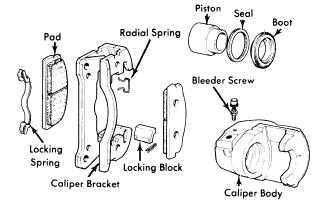
Removal - Raise and support vehicle, remove wheels. Plug master cylinder outlet parts. Disconnect brake line from caliper assembly. Remove cotter pins from locking blocks, drive out locking blocks and remove caliper. take out disc pads and springs. On models with rear disc brakes, parking brake must be disconnected.
NOTE - Pads MUST be replaced when worn to .079" (2mm) from original thickness.
Installation - To install caliper and pad assemblies, reverse removal procedure and note the following: Inside and outside pads may be different. When fitting pads to calipers, ensure distance between inner surfaces is not less than .413" (10.5 mm). In most instances two kinds of pads are available, be sure index point stripes are not mixed.
BRAKE ROTOR
Removal - Remove caliper as previously outlined. Before removing rotor check runout against specification. Runout should not exceed .006" (.15 mm). Remove caliper support bracket from support plate (front) or from axle housing (rear). Remove mounting rotor to wheel hub, remove hub plate, then remove rotor using a suitable drift or puller.
Installation - Fit rotor onto wheel hub, install attaching bolts and tighten evenly.
REAR BRAKE SHOES
Fig. 4 Typical Rear Drum Brake Assembly
for 128 Models
Removal - Raise and support rear of vehicle and remove wheels. Remove bolts attaching drum. Install a suitable tool to retain wheel cylinder pistons, remove upper and lower shoe return springs, shoe guide pins, springs, and cups, then remove brake shoes
Installation - To install, reverse removal procedure and bleed hydraulic system.
MASTER CYLINDER
Removal, Exc. X1/9 - Remove reservoir cover and plug fluid outlet line to prevent loss of fluid. On 128 models, remove spare tire. Disconnect fluid supply line at cylinder, hydraulic lines to front and rear brakes and nuts and washers retaining master cylinder to power unit. 
Installation - To install, reverse removal procedure and bleed hydraulic system.
Removal, X1/9 - Remove steering column. Disconnect hydraulic lines from reservoir. Remove mounting nuts and slide unit off supports. Disconnect outlet lines from master cylinder.
Installation - To install, reverse removal procedure and bleed hydraulic system.

OVERHAUL
Fig. 5 Front Brake Caliper Assembly
for 124 and 131 Models
Dissasembly, Front - With caliper assembly on bench, remove dust  boot. Apply light air pressure toNOTE - Be sure bore not scratched during removal process.
brake fluid inlet union and gently force piston from caliper. Remove piston seal from groove in piston cylinder bore.
Inspection - Clean all components in suitable solven (Fiat LDC). Inspect each part for damage or excessive wear. Replace all piston seals and dust boots. 
Reassembly - Fit piston seal in caliper. Insert piston to bottom end of cylinder bore. Piston dust boot on caliper body. Fit caliper body into caliper bracket and reinstall on vehicle.
Fig. 6 Front Brake Caliper Assembly
for 124 Models
Disassembly, Rear - With caliper assembly on bench, remove dust boot. With a screwdriver, separate piston from plunger. Remove piston seal from groove in piston cylinder bore. Remove cam lever, pivot
pin, and lever. Lift out self-adjusting plunger, plunger seal, disc spring, and spring thrust washer.
Inspection - Clean all components in suitable solvent (Fiat LDC). Inspect each part for damage or excessive wear. Replace all piston seals and dust boots.
Reassembly - Fit self-adjusting plunger complete with seal , disc springs, and thrust washer. Fit parking brake cam lever complete with pivot pin. Fit pivot pin bushing and snap ring. Fit piston sealing ring into caliper cylinder. Screw piston into cylinder until fully seated. Align piston slot so it is opposite bleed connection. Refit dust boot.

REAR WHEEL CYLINDER
Fig. 7 Exploded View of Rear Brake Caliper
for 124 Models
Disassembly - Remove boots, then remove pistons, seal rings, backing washers and reaction spring. Take out bleeder valve.
Inspection - Clean and dry all parts and inspect for excessive wear or damage. Light damage may be removed by honing; make sure bore size is not altered. Replace all rubber components at each overhaul.
Reassembly - To reassemble, reverse disassembly procedure and note the following: Lightly coat all parts with brake fluid. when assembling to prevent damage. Once assembled, move pistons to ensure they slide freely in cylinder bore.


MASTER CYLINDER
Fig. 8 Disassembled View of X1/9 Master Cylinder

Disassembly - Separate fluid inlet union from master cylinder. Disengage boot from cylinder body.
Fig. 9 Fiat Rear Wheel Cylinder Assembly
Back out set screws and end plug (if equipped). Remove the following components: Piston assemblies, return springs, cups, seal rings, and spacers.
Inspection - Clean and thoroughly dry all parts, then inspect for wear or damage. Light scoring may be remove by honing, make sure honing does not alter size of cylinder diameter. Replace all rubber pieces each time overhaul is performed.
Reassembly - To reassemble, reverse disassembly procedure and lightly coat all components with brake fluid before reassembly.


Fig. 10 Sectional View of Master Cylinder Assembly for 128 Models


Monday, July 2, 2012

FIAT 131 1975-77 Drive Axles Repair Guide

DESCRIPTION
Rear axle assembly uses an integral carrier type differential having hypoid type ring and drive pinion gear set. Drive pinion bearing preload is maintained by a collapsible spacer and differential bearing preload is obtained through the use of shims between the bearings and rear axle housing. Semi-floating axles use ball bearings retained on the axle by a press fit retaining ring and the axle is secured in the housing with a retaining flange. A removable rear cover permits inspection and service of differential assembly.
AXLE RATIO AND IDENTIFICATION
The fiat 131 uses only one rear axle assembly. The axle ratio is 4.44-1; a nine tooth drive pinion with a forty tooth ring gear.
REMOVAL AND INSTALLATION
Axle shafts and Bearings
 FIG. 1  SECTIONAL VIEW OF AXLE SHAFT
AND BEARING ASSEMBLY 
Removal - 1) Raise and support vehicle. Remove rear wheels and brake drums. Remove bolts retaining axle shaft retaining flange to brake backing plate.
2) Attach slide hammer to axle flange and pull axle from housing using care to guide the brake backing plate off the axle as if it is extracted.
3) Remove axle bearing from shaft using an arbor press and suitable support tools. Discard axle shaft bearing retainer. Inspect retainer seat on axle shaft and if seat is scored or damaged, replace axle shaft.
Installation - 1) Place retainer flange and bearing on axle shaft. Heat bearing retaining ring to about 600°F (300°C) and place heated retainer on axle shaft.
2) Using an arbor press and appropriate support tools, press bearing retainer onto shaft until bearing is locked between retainer and shoulder on axle shaft. NOTE - Do not exceed 13,000 lbs. force with press as damage to axle shaft assembly may occur.
3) If axle is to be installed at this time, replace oil seal inside axle housing (if required), and install axle in reverse order of removal.

REAR AXLE ASSEMBLY
Removal - Raise and support vehicle. Release parking brake and remove spring from parking brake bracket and support. Pull cable housings away from bracket and remove cables from bracket and support. Remove propeller shaft from drive pinion flange and stabilizer bars from rear axle housing. Remove brake hose from "T" connector and slip link out of slot in bracket on axle housing. Support rear axle assembly floor jack(s), remove shock absorber-to-axle housing bolts and lower and remove axle assembly.
Installation - Reverse removal procedure then bleed the brake system and check for proper operation of parking brake.

OVERHAUL
Disassembly
FIG. 2 REMOVING DIFFERENTIAL
BEARINGS FROM CASE
NOTE - Overhaul of differential assembly can be accomplished with rear axle assembly installed in vehicle
Differential Case Assembly - 1) Raise and support vehicle, remove axle shafts as previously described, and separate propeller shaft from drive pinion flange. Remove cover from rear of housing and drain lubricant.
2) Install spreader (8064), on housing, mark differential bearing caps for reference at time of reassembly, the remove bearing caps. Spread housing and remove differential case along with bearings and shims, noting position of bearing outer race and shims and keeping all left and right side components separated.
3) Using a puller, remove differential bearings from case. Keep bearings separated with other components. Put locating reference marks on ring gear and case, then removing eight ring gear-to-case retaining bolts and remove ring gear. NOTE - Drive ring gear from case (if required) using a soft headed mallet.
FIG. 3 EXPLODED VIEW OF FIAT 131 DIFFERENTIAL ASSEMBLY

4) Using a soft drift, drive differential pinion gear shaft out of case. Remove pinion gears, side gears, and side gear thrust washers.
Drive Pinion Gear - Hold drive pinion flange and remove flange nut and flange from drive pinion gear. Remove oil seal and dust shield from pinion shaft then push dive pinion gear out of rear housing. Remove drive pinion  bearing outer races from housing. Using an arbor press, remove rear bearing from drive pinion shaft and retain shims found between bearing and gear.

REASSEMBLY AND ADJUSTMENT
FIG. 4 REMOVING REAR BEARING
FROM DRIVE PINION GEAR
Drive Pinion Gear - 1) Install pinion bearing outer races in rear axle housing. Before installing rear bearing on drive pinion gear, establish pinion depth adjusting shim thickness as follows (all values given are in hundredths of a millimeter):
NOTE - If the original ring and pinion gears will be used for reassembly, and right-to-drive pinion gear tooth contact pattern is satisfactory, use original shim(s).
Note marking on original drive pinion shaft. Measure original shim thickness and add it to the value give on the pinion shaft to establish the nominal dimension.
Example: Pinion marking is +10 and original shim thickness is 2.90. Nominal dimension is 3.00 (2.90 plus +10).
Note marking on new pinion gear and subtract this value from the established nominal dimension and this will give you the new required shim thickness.
EXAMPLE: Nominal dimension is 3.00 and marking on new drive pinion is +20, then new shim thickness is 2.80 (3.00 minus +20, then new shim thickness is 2.80 (3.00 minus +20).
2) Place new (or original) pinion depth adjusting shim on drive pinion gear, and using a press install rear bearing on drive pinion gear. Lubricate bearing and install drive pinion and bearing in housing. Install new collapsible spacer, front pinion bearing, dust shield, new oil seal, and pinion flange in housing.
3) Start pinion flange nut on shaft and as nut is tightened, keep checking rotating torque of pinion shaft (pinion bearing preload) using an inch pound torque wrench. Tighten nut until pinion bearing preload is within specifications. NOTE - If pinion bearing preload torque is exceeded, do not back off nut to obtain preload. Install new collapsible spacer and repeat procedure.
Differential Case Assembly - 1) Place thrust washers on side gears and install side gears in case. Install pinion gears by rolling them into position and install pinion shaft. Check rotating torque is not to specification, install new thrust washers on side gears. NOTE -Thrust washers are available in thicknesses from .0709" (1.80 mm) to .0817" (2.10 mm) in increments of .002" (.05 mm).
2) Install ring gear on case and tighten bolts to specified torque. Press differential bearings onto case, and if using original bearings, spread housing and install case using original shims. If using new bearing or case, install case in housing and insert enough shims equally on both sides to eliminate any end play.
3) Install bearing caps and bolts and tighten bolts. Measure ring gear backlash using a dial indicator mounted to hoousing ring gear backlash using a dial indicator mounted to housing with plunger contacting ring gear at right angel to the gear teeth. Block drive pinion flange from turning. Zero dial indicator. Rotate ring geaer back as far as possible and note backlash reading on indicator. If backlash is not within specification, adjust backlash by changing size of shims. To increase backlash, increase size of shim on pinion side of carrier, and to decrease backlash, increase size of shim on ring gear side of carrier. When changing shims, be sure to install shims of equal size to opposite side of carrier.
4) After determining correct shims to be used, add .002" (.05 mm) more shim thickness to each side. Install spreader on housing, spread housing and install bearing outer races and shims. Remove spreader and install bearing caps and tighten bolts. With differential completely assembled, check ring-to-pinion gear tooth contact pattern to ensure all adjustments are correct.

Fiat 124 1975-77 Drive Axles Repair Manual

DESCRIPTION
Rear axle assembly is semi-floating, hypoid gear type with centerline of pinion set below centerline of ring gear. Axle shafts have integral wheel hubs and are supported in the differential case by side gears and in the axle housing by ball bearings. Service of these assemblies, with exception of axle housing, may be performed without removing complete rear axle assembly from vehicle.
AXLE RATIO IDENTIFICATION
The semi-floating, hypoid gear type rear axle assembly with separate housing is used on all Fiat models, The axle ration is 4.3-1.
REMOVAL AND INSTALLATION
Axle Shafts and Bearings
Removal - 1) Raise vehicle and remove rear wheels and disc brake front shield. Remove caliper support bracket mounting bolt and remove caliper (without disconnecting brake lines). Remove bolts attaching brake disct to axle shaft hub and remove brake disc and plate.
2) Remove snap ring securing bearing dust shield. Attach slide hammer and withdraw axle shaft assembly. Inspect axle shaft bearing, dust shield and bearing retaining collar for wear or damage and replace as necessary.
Disassembly - Using suitable arbor press (A. 74108/1/2), press bearing retaining collar off axle shaft and discard collar. NOTE - Retaining collar must never be reused; replace with new collar. Remove snap ring, dust shield and bearing. If axle shaft is score or damaged, replace shaft.
Reassembly - 1) Install snap ring, dust shield and bearing onto axle shaft held vertically on solid plate of arbor press (A. 74107/1). Insert new collar into suitable holder (A. 74107/4), place in oven and heat to 571°±18°F (300°±10°C). Remove unit from oven and plae on axle shaft. Press axle shaft into collar using 13,000 lb (6,000 kg) maximum pressure.
2) Place axle shaft assembly in tool A. 9560. Position dial indicator to contact hub of axle shaft. Apply 4400 lbs. (2000 kg) axial load with tool A. 95601. Rotate axle by applying 58 to 61.5 ft. lbs. to 8.5 mkg) of torque then check dial indicator reading at opposite end of axle shaft. Reading should remain at zero during rotation of axle shaft.
3) Remove load from axle and recheck dial indicator for zero reading. This will insure that collar has not moved on axle shaft.
Installation - Install new oil seal and "O" ring and complete installation by reversing removal procedure.
FIG 1. CHECKING FIT OF AXLE SHAFT BEARING RETAINER AND AXIAL LOAD


DIFFERENTIAL CARRIER
Removal - Drain fluid, raise vehicle, and remove wheels. Withdraw axle shafts for enough to disengage from side gears. Disconnect propeller shaft, support differential and remove attaching bolts. Remove differential assembly from axle housing.
Installation - Thoroughly clean oil residue from axle housing. Position new gasket in place and reverse removal procedure.

OVERHAUL
Disassembly - 1) With differential secured in suitable holding fixture, remove two bolts and spring washers from caps and remove lock plates. Remove bolts and spring washers securing case bearing caps, and remove caps, adjuster rings and roller bearing cups. Remove differential case from carrier.
2) Turn differential carrier upside down and lock bevel pinion in place. Loosen self-locking nut securing sleeve to bevel pinion shaft and remove sleeve. Remove pinion, thrust ring, rear roller bearing cone and collapsible spacer from inside housing. Remove oil seal, oil slinger, and front bearing cone from carrier.
3) Slide collapsible spacer off pinion, then draw off rear roller bearing .Thrust washer can then be removed from pinion. Using a suitable puller, remove differential case roller bearings. Remove screws holding ring gear to differential case roller bearings. Remove screws holding ring gear to differential case then use drift to remove pinion gear from case. Remove pinion gears, side gears, and thrust washers.

REASSEMBLY AND ADJUSTMENT
FIG 3. CHECKING FOR CORRECT
THICKNESS OF WASHER FOR DRIVE
PINION DEPTH ADJUSTMENT
Case Assembly - 1) Install thrust washers on differential side gears and position gears in differential case. Insert pinion gears in case and engage them with side gears. Align holes in pinion gears through openings in case and insert pinion shaft. Check axial play in each side gear.
2) Axial play should not exceed .004" (.10 mm). If play exceeds specification, replace side gear thrust washers. These washers are available in various thicknesses. If correct clearance cannot be obtained, gears must be replaced. Assemble ring gear to differential case and torque to specification. Using suitable driver (A. 70152), install both roller bearings on differential case.
Drive Pinion Depth - 1) Fit front and rear roller bearing cups of bevel pinion in position using suitable driver. Using same driver, attach cone  of rear roller bearing to dummy pinion (A. 70184) then position dummy pinion in differential carrier.
FIG. 4 LOCATION OF STAMPED NUMBER
ON DRIVE PINION GEAR
2) Install cone on front roller bearing and place nut on dummy pinion. Turn pinion to seat bearing cones and tighten nut.
3) Zero dial indicator (A. 95690) on a surface plate then attach to dummy pinion. Position dial indicator to allow plunger to contact roller bearing seat in differential case. Obtain minimum reading on dial indicator by moving plunger from right to left. Record reading and repeat procedure on opposite side.
4) Determine on average from the two readings, then from this average, subtract the value stamped on bevel pinion to be used. This will give correct thickness of thrust washers to be inserted between the head of the pinion and the shoulder of rear roller bearing.
5) If the number stamped on the pinion is preceded by a plus sign, the thickness of the washer to be used is derived by subtracting this number from the dial gauge reading. If the number stamped on the pinion is preceded by a minus sign, the thickness of the washer is obtained by adding this figure to the dial gauge reading.
FIG. 5 CHECKING DIFFERENTIAL BEARING
AND RING GEAR BACKLASH
6) Place thrust washer (correct thickness) on bevel pinion, then rear roller bearing cone followed by collapsible spacer. Install pinion assembly in carrier and attach the front roller bearing cone, oil slinger, oil seal, and "U" joint sleeve. Install washer and self-locking nut on tail of pinion.
Pinion Bearing Preload - Secure pinion to keep it from turning. Gradually tighten nut on tail of pinion shat to 87-166 ft. lbs. (12-23 mkg). Check turning torque of pinion shaft using dynamometer (A.95697) and adapter (A. 55075) fitted to pinion nut and set to 17 INCH lbs. (20 cmkg). If turning torque is less than 14 INCH lbs. (16 cmkg), pinion nut must be tightened (without exceeding maximum torque). If turning torque is more than 17 INCH lbs. (20 cmkg), pinion must be removed an collapsible spacer changed.
Backlash and Side Bearing Preload - 1) Place differential side bearing cups on side bearings and place differential assembly into carrier. Fit two bearing retaining and adjusting rings, install caps and torque to specifications.
2) Attach suitable tool (A. 95688)  (see illustration), to differential carrier. Adjust backlash between ring gear and pinion to .0031-.0051" (0.08-0.13 mm). Insure that bearings are not preloaded.
3) Set preload by tightening two bearing adjusting rings alternately with equal number of turns until dial indicator "A" (see illustration), shows an increase of .0055-.0071" (0.14-0.18 mm). After preload is set, check backlash of bevel gears.
4) To check backlash, set dial indicator to "B" (see illustration), so that plunger rests against tooth of bevel gear. Rotate gear to obtain maximum reading. Backlash must be .0031-.0051" (0.08-0.13 mm).
Final Inspection and Assembly - With pinion bearing and ring gear backlash properly adjusted, make a tooth contact pattern check. NOTE - Check gear tooth contact using paint impression method described at beginning of this section. When pattern is satisfactory, install axle shafts, brake drums, wheels and tires, propeller shaft and refill with suitable gear lubricant.

Tuesday, April 3, 2012

Fiat 124 1968-74 Axles Repair Manual

FIAT 124 (1968-74)

DESCRIPTION
Rear axle assembly is semi-floating, hypoid gear type with centerline of pinion set below centerline of ring gear. Axle shafts have integral wheel hubs and are supported in the differential case by side gears and in the axle housing by ball bearings. Service of these assemblies, with exception of axle housing, may be performed without removing complete rear axle assembly from vehicle
AXLE RATIO IDENTIFICATION
The semi-floating, hypoid gear type rear axle assembly with separate housing is used on all Fiat 124 models. The basic difference in rear axles from one vehicle model to another is the axle ratio. The Fiat 124 Sedan axle ratio is 4.3 to 1, and the Fiat 124 Sedan Special is 4.1 to 1.
REMOVAL AND INSTALLATION
Axle Shaft and Bearings
Removal - 1) Raise vehicle and remove rear wheels and disc brake front shield. Remove caliper support bracket mounting bolt and remove caliper (without disconnecting brake lines). Remove bolts attaching brake disc to axle shaft hub and remove brake dis and plate.
2) Remove snap ring securing bearing dust shield. Attach slide hammer and withdraw axle shaft assembly. Inspect axle shaft, bearing, dust shield and bearing retaining collar for wear or damage and replace as necessary.
Disassembly - Using suitable arbor press (A. 74108/1/2), press bearing retaining collar off axle shaft and discard collar. NOTE - Retaining collar must never be reused; replace with new collar. Remove ring, dust shield, and bearing. If axle shaft is scored or damaged, replace shaft.
Reassembly - 1) Install snap ring, dust shield, and bearing onto axle shaft held vertically on solid plate of arbor press (A. 74107/1). Insert new collar into suitable holder. (A. 74107/4), place in oven and place on axle shaft. Press axle into collar using 13,000 lbs (6000 kg) maximum pressure.
2) Place axle shaft assembly in tool A. 9560. Rotate axle by applying 58 to 61.5 ft. lbs. (8 to 8.5 mkg) of torque then check dial indicator reading at opposite end of axle shaft. Reading should remain at zero rotation of axle shaft.
3) Remove load from axle and recheck dial indicator to zero reading. This will insure that collar has not moved on axle shaft.
Reinstallation - Install new oil seal and "O" ring and complete installation by reversing removal procedure.

DIFFERENTIAL CARRIER
Removal - Drain fluid, raise vehicle, and remove wheels. Withdraw axle shafts for enough to disengage from side gears. Disconnect propeller shaft, support differential and remove attaching bolts. Remove differential assembly from axle housing.
Installation - Thoroughly clean oil residue from axle housing. Position new gasket in place and reverse removal procedure.
CHECKING AXIAL LOAD


OVERHAUL
Disassembly - 1) With differential secured in suitable holding fixture, remove two bolts and spring washers from caps and remove lock plates. Remove bolts and spring washers securing case bearing caps, and remove caps, adjuster rings and roller bearing cups. Remove differential case from carrier.
2) Turn differential carrier upside down and lock bevel pinion shaft and remove sleeve. Remove pinion, thrust ring, rear roller bearing cone and collapsible spacer from inside housing. Remove oil seal, oil slinger, and front bearing cone from carrier.
3) Slide collapsible spacer off pinion, then draw off rear roller bearing. Thrust washer can then be removed from pinion. Using a suitable puller, remove differential case roller bearings. Remove screws holding ring gear to differential case then use drift to remove pinion gear from case. Remove pinion gears, side gears and thrust washers.

REASSEMBLY AND ADJUSTMENT
Case Assembly - 1) Install thrust washers on differential side gears and position gears in differential case. Insert pinion gears in case and engage them with side gears. Align holes in pinion gears through openings in case and insert pinion shaft. Check axial play in each side gear.
2) Axial play should not exceed .004" (0.10 mm). If play exceeds specification, replace side gear thrust washers. These washers are available in various thicknesses. If correct clearance cannot be obtained, gears must be replaced. Assemble ring gear to differential case and torque to specification. Using suitable driver (A. 70152), install both roller bearings on differential case.
CHECKING FOR CORRECT
THICKNESS OF BEVEL PINION
REAR BEARING THRUST WASHER
Drive Pinion Depth - 1) Fit front and rear roller bearing cups of bevel pinion in position using suitable driver. Using same driver, attache cone of rear roller bearing to dummy pinion (A. 70184) then position in differential carrier.
2) Install cone on front roller bearing and place nut on dummy pinion. Turn pinion to seat bearing cones and tighten nut.
3) Zero dial indicator (A. 95690) on a surface plate then attach to dummy pinion. Position dial indicator to allow plunger to contact roller bearing seat in differential case. Obtain minimum reading on dial indicator by moving plunger from right to left. Record reading and repeat procedure on opposite side.
4) Determine an average from the two readings, then from this average, subtract the value stamped on bevel pinion to be used. This will give correct thickness of thrust washers to be inserted between the head of the pinion and the shoulder of rear roller bearing.
STAMPED NUMBER LOCATION ON
BEVEL PINION
5) If the number stamped on the pinion is preceded by a plus sign, the thickness of the washer to be used is derived by subtracting this number from dial gauge reading. If the number stamped on the pinion is preceded by a minus sign, the thickness of the washer is obtained by adding this figure to the dial gauge reading.
6) Place thrust washer (correct thickness) on bevel pinion, then rear roller bearing cone followed by collapsible spacer. Install pinion assembly in carrier and attach the front roller bearing cone, oil slinger, oil seal and "U" joint sleeve. Install washer and self-locking nut on tail of pinion.

Pinion Bearing Preload - Secure pinion to keep it from turning. Gradually tighten nut on tail of pinion shat to B7-166 ft. lbs. (12-23 mkg). Check turning torque of pinion shaft using dynamometer (A. 95697) and adapter (A.55075) fitted to pinion nut and set to 17 INCH lbs. (20 cmkg). If turning torque is less than 14 INCH lbs. (16 mkg), pinion nut must be tightened (without exceeding maximum torque). If turning torque is more than 17 INCH lbs. (20 cmkg), pinion must be removed and collapsible spacer changed.

CHECKING PRELOAD OF DIFFERENTIAL
CASE BEARINGS AND BACKLASH
OF BEVEL GEAR
Backlash and Side Bearing Preload - 1) Place differential side bearing cups on side bearings and place differential assembly into carrier. Fit two bearing retaining and adjusting rings, install caps and torque to specifications.
2) Attach suitable tool (A. 95688) (see illustration), to differential carrier. Adjust backlash between ring gear and pinion to .0031-.0051" (0.08-0.13 mm). Insure that bearings are not preloaded.
3) Set preload by tightening two bearing adjusting rings alternately with equal number of turns until dial indicator "A" (see illustration), shows an increase of .0055-.0071" (0.14-0.18 mm). After preload is set, check backlash of bevel gears.
4) To check backlash, set dial indicator "B" (see illustration), so that plunger rests against tooth of bevel gear. Rotate ring gear to obtain maximum reading. Backlash must be .031-.0051" (0.08-0.13 mm).
Final Inspection and Assembly - With pinion bearing and ring gear backlash properly adjusted, make a tooth pattern contact check. NOTE - Check gear tooth contact using point impression mothod described at beginning of this section. When pattern is satisfactory, install axle shafts, brake drums, wheels and tires, propeller shaft and refill with suitable gear lubricant.

Wednesday, November 30, 2011

1975 Fiat Wheel Alignment Guide

FIAT SPECIFICATIONS AND ADJUSTMENT

TIRE INFLATION (COLD)
Before attempting to check or adjust wheel alignment, make sure tires are properly inflated. Refer to manufacturers specifications given in owner's manual.

CASTER
Model 131 and 128 (Except. Sport L) - If caster is not to specifications, raise front of vehicle. Remove stabilizer bar-to-control arm nut and disconnect control arm from body. Remove end of stabilizer bar from control arm. To adjust caster, addition of shims between end of stabilizer bar and rubber pad of control arm will decrease caster angle and removal of shims will increase caster angle. Reverse removal procedure and recheck caster.

Model 128 Sport L - If caster is not to specifications, adjust by adding or removing shims located between stabilizer bar bushing and frame.

Model 124 - If caster is not within specifications, raise front of vehicle and remove wheel and shock absorber. Using suitable tool (A.74174), compress spring to relieve lower control arm and loosen nuts holding control arm pivot bar to crossmember. To adjust caster, remove shims from front stud and move to rear stud to increase caster. To decrease caster, remove shims from rear stud and move shims to front stud. Reverse removal procedure and check caster.

Model X1/9 - If caster is not to specifications, adjust by adding or removing shims located between stabilizer bar and stabilizer bar support.

CAMBER
Model 124 - If camber is not within specifications, adjust by changing shims. Raise front of vehicle, remove wheel and shock absorber. Using suitable tool (A.74174), compress spring to relieve lower control arm and loosen nuts holding control arm pivot bar to crossmember. To increase camber, remove equal amount of shims from both studs and add equal amount of shims to decrease camber. NOTE -  Adding or removing equal amounts of shims will not affect caster. Reverse removal procedure and check camber.

Model 128 and 131 Front - Camber is nonadjustable. If not within specifications, inspect suspension for damage and repair or replace parts as necessary.

Model 128 Rear - If rear camber is not within specifications raise rear of vehicle and compress one end of leaf spring, shifting it from flexible guide anchoring spring to control arm. Remove guide and slowly release spring. Remove nuts attaching pivot to body and loosen screw to free adjustment shims. To increase camber, add an equal number of shims on both screws attaching control arm to body. To decrease, remove equal number of shims from both screws. Reverse removal procedure and check camber.

Model X1/9 Front and Rear - Camber is nonadjustable. If not within specifications, inspect suspension for damage and repair or replace parts as necessary.

TOE-IN
Model 128, 131 and X1/9 Front - Place front wheels in straight-ahead position. If toe-in is not within specifications, loosen sleeve locking nut on tie rods. To adjust, rotate hexagon on ball pin to set toe-in specifications. Hold hexagon in position and lock nut against tie rod sleeve.

Model 128 Rear - If rear toe-in is not within specifications raise rear of vehicle and compress one end of leaf spring, shifting it from flexible guide anchoring spring to control arm. Remove guide and slowly release spring. Remove nuts attaching pivot to body and loosen screws to free adjustment shims. To increase to-in, add shims to rear screw or remove shims front front screw. To decrease, add shims to front screw or re3move shims from rear screw.

Model 124 Front - Place front wheels in straight-ahead position. If toe-in is not within specifications, loosen four clamps securing sleeves on tie rods. Rotate tie rods in opposite direction (by equal amounts) to set toe-in to specifications. Tighten clamp nuts. NOTE - Expansion slot in sleeve must coincide with clamp joint when clamp is fully tightened.

Model X1/9 Rear - If rear toe-in is not within specifications, loosen clamps securing sleeves to reaction rods. Adjust toe-in by lengthening or shortening reaction rods. Tighten clamps and recheck toe-in.


1963-73 Fiat Models Wheel Alignment Guide

1963-73 FIAT SPECIFICATIONS AND ADJUSTMENTS

TIRE INFLATION (COLD)
Before attempting to check or adjust wheel alignment, ensure that tires are inflated according to specifications


CASTER
Model 128 - If caster is not within specifications, raise front of vehicle. Remove anti-roll bar to control arm nut and disconnect control arm from body. Remove end of anti-roll bar from control arm. To adjust caster, addition of shims between end of anti-roll bar and rubber pad of control arm will decrease caster and removal of shims will increase caster. Reverse removal procedure and check caster.

Model 124 - If caster is not within specifications, raise front of vehicle and remove wheel and shock absorber. Using suitable tool (A.741174), compress spring to relieve lower control arm and loosen nuts holding control arm pivot bar to crossmember. To adjust caster, remove shims from front stud and move to rear stud to increase caster. To decrease caster, remove shims from rear stud and move shims to front stud. Reverse removal procedure and check caster.

Models 600D, 850 and 1100R - If caster is not within specifications, loosen two nuts on control arm pivot bar to body. To adjust, remove shims from rear stud and place shims at front stud to increase caster. To decrease caster, move shims from front stud to rear stud. Tighten nuts and check caster.

Model 1500 - No adjustment procedure available.

CAMBER
Model 124 - If camber is not within specifications, adjust by changing shims. Riase front of vehicle, remove wheel and shock absorber. Using suitable tool (A.74174), compress spring to relieve lower control arm and loosen nuts holding control arm pivot bar to crossmember. To increase camber, remove equal amount of shims from both studs and add equal amount of shims to decrease camber. NOTE - Adding or removing equal amounts of shims will not affect caster. Reverse removal procedure and check camber.

Model 1500 - No adjustment procedure available at time of this publication. See Wheel Alignment specifications.


Model 128 - Front - Camber is nonadjustable. If not within specifications, inspect suspension for damage. Repair or replace parts as necessary.

Model 128 Rear - If rear camber is not within specifications raise rear of vehicle and compress one end of leaf spring, shifting it from flexible guide anchoring spring to control arm. Remove guide and slowly release spring. Remove nuts attaching pivot to body and loosen screw to free adjustment shims. To increase camber, add an equal number of shims on both screws attaching control arm to body. To decrease, remove equal number of shims from both screws. Reverse removal procedure and check camber.

Models 600D, 850 and 1100R Front - If camber is not within specifications, adjust by changing shims. Loosen two nuts on control arm pivot bar to body. To increase camber, add equal amounts of shims to both studs and to decrease, remove equal amounts of shims. Tighten nuts and check camber.

TOE-IN
Model 128 Front - Place front wheels in straight-ahead position. If toe-in is not within specifications, loosen sleeve locking nut on tie rods. To adjust, rotate hexagon on ball pin to set toe-in specifications. Hold hexagon in position and lock nuts against tie rod sleeve.

Model 128 Rear - If rear toe-in is not within specifications raise rear of vehicle and compress one end of leaf spring, shifting it from flexible guide anchoring spring to control arm. Remove guide and slowly release spring. Remove nuts attaching pivot to body and loosen screws to free adjustment shims. To increase toe-in, add shims to rear screw or remove shims from front screw. To decrease, add shims to front screw or remove shims from rear screw.

All Other Models Front - Place front wheels in straight ahead position. If toe-in is not within specifications, loosen four clamps securing sleeves on tie rods. Rotate tie rods in opposite direction (by equal amounts) to set toe-in to specifications. Tighten clamps. NOTE - Expansion slot in sleeve must coincide with clamp joint when clamp is fully tightened.

Model 600D and 850 Rear - If rear is not within specifications, loosen screws securing lower control arm support to body. Elongated holes on support allow movement to set toe-in to specifications. Tighten screws 29-36 ft lbs. and check toe-in.